Do you have a question about the Yaesu FL2100 and is the answer not in the manual?
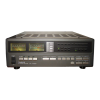
Details its use of 572B/T160 triodes, cooling, ALC, and SWR bridge.
Warns against operating with the top shield cover removed due to high voltage.
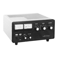
Describes the function of POWER-OFF and OPER-STBY switches.
Explains SWR-IP, F-R, SENS, and PLATE controls.
Explains wiring for 117V/220V operation and cautions against improper voltage.
Instructions for connecting a short, heavy gauge wire to the 'GND' post.
Warns against operating without earth ground and an antenna or dummy load.
Emphasizes connecting to antenna/load and correct power connection before operating.
Steps for tuning up the exciter and amplifier for operation.
Steps for turning on the amplifier, adjusting plate current, and tuning controls.
How to measure relative power output and SWR using meter settings.
Extreme caution is advised before making adjustments inside the cabinet.
Schematic of the high voltage power supply, including safety lock and meter connections.
Diagram of the RF amplifier stage, including tubes, input/output tuning, and switching.
Diagram showing ALC, SWR bridge, and control/metering connections.
| Type | Linear Amplifier |
|---|---|
| Input Impedance | 50 Ohms |
| Tube Complement/Type | 2 x 572B |
| Power Supply | Internal |
| Tuning | Manual |
| Input Power | 100 Watts |
| Power Requirements | 50/60 Hz |