Do you have a question about the Yaesu FL-110 and is the answer not in the manual?
Details the FL-110's solid-state linear amplifier design and push-pull circuit.
Warns against exceeding rated drive power to prevent PA transistor destruction.
Lists the integrated circuits, transistors, and diodes used in the amplifier.
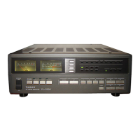
Details the function of the POWER, DELAY, BAND controls and REC, OPER, AFP indicators.
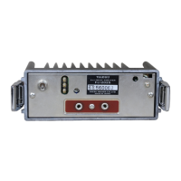
Explains the INPUT, ANT, POWER, PTT, and GND connections and controls.
Warns that incorrect DC power polarity will cause permanent damage and void the warranty.
Covers power source, ventilation, and antenna SWR for optimal performance and protection.
Explains manual/automatic keying and PTT switch polarity for different transceivers.
Stresses not to exceed 15 watts drive power and to always connect an antenna before keying.
Explains the AFP circuit warning lamp indicates a malfunction, possibly due to antenna or overdrive.
Details the four main parts: Coupling Unit, Control Unit, Booster Unit, and LPF unit.
Explains the push-pull amplifier stage using SRF-1427 transistors and negative feedback.
Lists precautions for power voltage, environment, and ventilation to prevent damage.
Procedure to adjust the relay hold time using VR201.
Steps to balance the CM coupler using TC101 and TC301 for minimum VTVM readings.
Procedure to adjust the Automatic Final Protection circuit for correct operation.
Adjusts the carrier control circuit using VR101 to activate the relay.
Procedure to set PA collector idle current when PA transistors are replaced.
Lists components for various units including Main Chassis, Coupler, Booster, Control, and LPF.
Lists associated accessories, cables, and fuses.