Do you have a question about the Yaesu FT-480R and is the answer not in the manual?
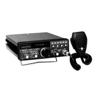
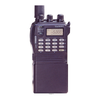
Overview of the FT-480R transceiver's capabilities, features, and revolutionary aspects.
Detailed technical specifications including frequency coverage, modes, and power output.
Lists of semiconductor components and optional accessories available for the FT-480R.
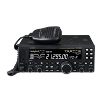
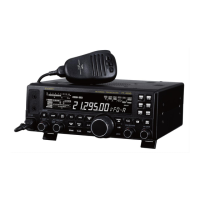
Identification and functional explanation of front panel controls and indicators.
Details on rear panel connectors, switches, and their respective functions.
Explanation of the switches located beneath the transceiver's cabinet.
Instructions for proper installation in mobile and base station configurations.
Guidance on basic operating procedures and initial setup checks.
Collection of block diagrams illustrating the transceiver's internal circuitry for various functions.
Detailed block diagram for the Single Sideband (SSB) and Continuous Wave (CW) reception paths.
Detailed block diagram for the Frequency Modulation (FM) reception path.
Detailed block diagram for the Single Sideband (SSB) transmit path.
Detailed block diagram for the Continuous Wave (CW) transmit path.
Detailed block diagram for the Frequency Modulation (FM) transmit path.
Explanations of the functional operation of key circuits within the transceiver.
Information and specifications for the optional FP-80 power supply unit.
Diagram illustrating the frequency relationships between different stages of the transceiver.
Table listing crystal specifications, including frequency, holder, and load capacitance.
Step-by-step instructions for safely disassembling the transceiver's outer casing.
An illustrated exploded view of the transceiver's components for easier identification.
Diagrams showing the physical layout of components on the main circuit boards.
Best practices and precautions for soldering and desoldering electronic components.
Methods and techniques for repairing damaged conductive traces on printed circuit boards.
Procedures for modifying the transceiver, such as frequency range adjustments.
Detailed schematic diagrams illustrating the interconnections of various components and units.
Visual guides showing the placement of components on specific circuit boards.
Diagrams showing signal amplitude levels at key test points in the receiver section.
A chart listing expected DC voltage readings at various test points for troubleshooting.
Logic charts detailing the operation of the Phase-Locked Loop (PLL) control unit.
Procedures for performing regular maintenance and precise alignment for optimal performance.
Systematic approach to diagnosing and resolving common equipment malfunctions.
Diagnostic flowcharts to identify the root cause of specific operational faults.
Guidelines and examples for ordering necessary spare parts for the transceiver.
An extensive catalog of all replaceable parts, including their part numbers and designations.
| Brand | Yaesu |
|---|---|
| Model | FT-480R |
| Category | Transceiver |
| Language | English |