Do you have a question about the Yale OS030EC and is the answer not in the manual?
Provides a general description of the frame parts, including weldments, doors, and covers.
Details the frame's mounts for various systems like upright, steering, and electrical components.
Procedure for removing frame components, with crucial safety warnings for material decomposition.
Instructions for removing protective covers, panels, and plates to access internal parts.
Description of the caster unit, its function, and its connection to the forklift frame.
Step-by-step instructions for replacing the entire caster assembly on the lift truck.
Procedure for replacing individual caster wheels, emphasizing replacing them as a set.
General safety guidelines and precautions applicable to maintenance and repair operations.
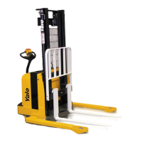
This document outlines the service and maintenance procedures for a range of Yale Order Selector lift trucks, specifically models SS030BF [A474], FS030BF [A497], OS030EC [C801], OS030EF [D801], OS/SS030BE [D826], and OS030BF [E826]. The manual is structured to provide comprehensive guidance on various components and systems of these industrial vehicles, ensuring their safe and efficient operation and upkeep.
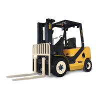
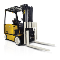
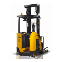
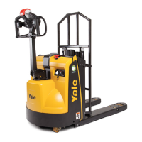
The primary function of these devices is to serve as order selectors, designed for lifting and transporting goods within a warehouse or industrial setting. They enable operators to pick items from various heights, facilitating efficient inventory management and order fulfillment. The design emphasizes stability and maneuverability, crucial for navigating confined spaces and handling diverse loads.
Key usage features are integrated throughout the design. The frame, a fundamental component, provides the structural integrity for the entire lift truck. It incorporates mounts for the upright assembly, steering system, electrical system, and hydraulic system, as well as doors, access panels, and covers. The outer channel of the upright and the base arms are integral parts of the frame weldment, contributing to the overall stability and load-bearing capacity. The steering system allows for precise control, essential for navigating aisles and positioning the truck accurately. The brake system ensures safe stopping and control, a critical safety feature in any industrial vehicle. Hydraulic systems, including the gear pump, facilitate lifting and lowering operations, enabling the operator to access goods at different elevations. The electrical system, with its dedicated controller, manages various functions and ensures reliable operation. Wire guidance features are also available, enhancing precision and efficiency in guided aisle applications.
Maintenance features are extensively detailed to ensure the longevity and safe operation of the lift trucks. The manual provides specific instructions for maintaining the DC motor, a critical component for propulsion. Procedures for AC motor repair are also outlined, covering models with specific serial number ranges (S/N A474N03000L=> S/N A497N030000L=> S/N D801N02161L=> S/N E826N01917L=>). The master drive unit, another essential part of the propulsion system, has dedicated maintenance guidelines, including specific instructions for units within certain serial number ranges (S/N D801N03000L=> S/N A474N03000L=> S/N A497N030000L=> S/N E826N03000L=>).
The manual also covers the maintenance of various structural and operational components. Frame repair instructions address general descriptions, removal and disassembly of covers, panels, and plates, as well as the caster and caster wheels. The caster, which provides support for the front of the lift truck, is an articulated axle design, allowing both wheels to maintain equal weight distribution for better operation and wear. Instructions are provided for replacing the entire caster assembly or individual caster wheels, emphasizing the importance of replacing wheels as a set to prevent uneven wear.
User interface functions are detailed, with specific instructions for supervisor and service-level functions, categorized by serial number ranges. This ensures that operators and technicians can effectively interact with and diagnose issues within the system. Wire guidance systems also have dedicated maintenance sections.
Beyond mechanical and electrical systems, the manual addresses other crucial aspects of maintenance. Industrial battery maintenance is covered, ensuring proper care and longevity of the power source. Lift cylinders and mast components, including description and repair procedures, are detailed to maintain lifting capabilities. The manual also includes information on metric and inch (SAE) fasteners, ensuring correct hardware usage during repairs. Periodic maintenance schedules are provided, outlining routine checks and services necessary for optimal performance and safety. Diagrams are included to aid in visual identification of components and systems. Capacities and specifications are listed to provide essential operational data. Finally, controller diagnostics are covered, enabling technicians to troubleshoot and resolve issues related to the lift truck's control systems.
Safety precautions are paramount throughout the manual. General safety guidelines emphasize the importance of using proper lifting equipment, wearing safety glasses, disconnecting the battery connector before maintenance, and using correct blocks to prevent movement. The use of YALE APPROVED parts is mandated for repairs to ensure compatibility and performance. Fastening a "DO NOT OPERATE" tag during repairs is also a critical safety measure. Warnings and cautions are highlighted, particularly regarding flammable materials like gasoline, LPG, CNG, and diesel fuel, and the flammable gases generated by batteries during charging. Specific warnings are also given for handling polyurethane paint during welding or burning, due to the release of isocyanates, requiring adequate ventilation and respiratory protection.
The manual also provides instructions for painting and label replacement. Painting guidelines emphasize surface preparation, rust removal, priming, and the use of correct Yale paint. Label replacement instructions stress the importance of immediately replacing damaged warning or instruction labels, ensuring that critical safety and operational information remains visible and legible. This comprehensive approach to maintenance, coupled with a strong emphasis on safety, ensures that the Yale Order Selector lift trucks can be operated and maintained effectively and safely throughout their service life.