30 Connections and Setup
01V96i—Owner’s Manual
Signals that are currently assigned to the output
connectors are shown in the parameter boxes (
1)
underneath the connector numbers. The parameter
indicators are explained below:
• – ..........................................No assignment
• BUS1–BUS8 .....................Bus Out 1–8 signals
• AUX1–AUX8 ...................Aux Out 1–8 Signals
• ST L/R................................Stereo Out signals
• INS CH1–INS CH32......Input Channels 1–32
Insert Outs
• INS BUS1–INS BUS8 ....Bus Out 1–8 Insert Outs
• INS AUX1–INS AUX8 ..Aux Out 1–8 Insert Outs
• INS ST-L/ST-R ................Stereo Out Insert Outs
• CAS BUS1–BUS8 ...........Bus Out 1–8 Cascade
Outs
• CAS AUX1–AUX8..........Aux Out 1–8 Cascade
Outs
• CAS ST-L/ST-R ...............Stereo Out Cascade Outs
• CASSOLOL/CASSOLOR ..Solo Channel Cascade
Outs
2. Use the cursor buttons to move the cur-
sor to a patch parameter (
1) you wish to
change, and rotate the Parameter wheel
or press the [INC]/[DEC] buttons to mod-
ify the patching.
3. Press [ENTER] to confirm the change.
Patching output signals to USB
OUT
By default, the following output signals are assigned to
USB OUT.
• USB OUT1–8 ..... Bus Out 1–8 signals
• USB OUT9–16... Bus Out 1–8 signals
If you want to change or verify this patching, proceed as
follows.
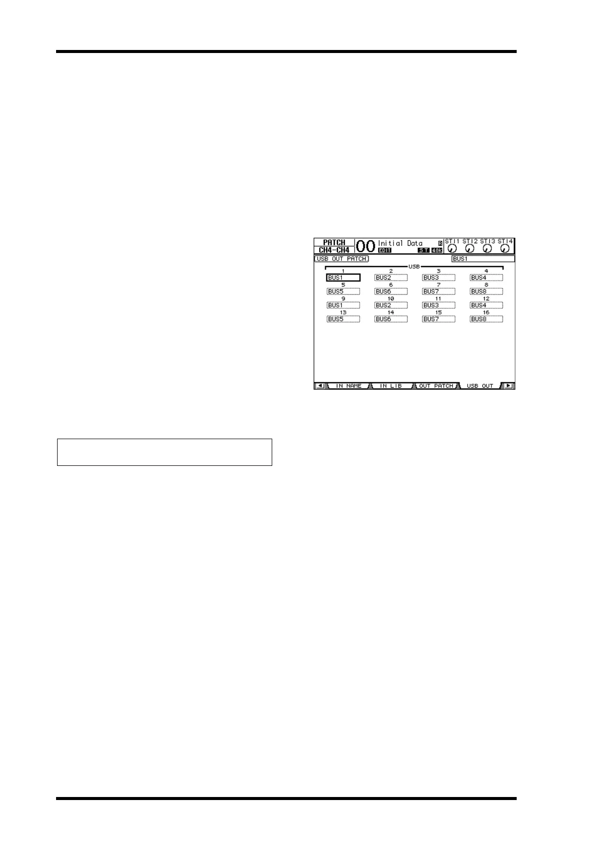
1. Press [PATCH] repeatedly until the fol-
lowing page appears.
The parameter boxes underneath each number
indicate the currently-assigned signal routing. The
meaning of these indicators are explained below.
• – ......................................... No assignment
• BUS1–BUS8..................... Bus Out 1–8 signals
• AUX1–AUX8................... Aux Out 1–8 signals
• ST L/R ............................... Stereo Out signals
• INS CH1–INS CH32..... Input Channels 1–32
Insert Outs
• INS BUS1–INS BUS8.... Bus Out 1–8 Insert Outs
• INS AUX1–INS AUX8.. Aux Out 1–8 Insert Outs
• INS ST-L/ST-R................ Stereo Out Insert Outs
2. Move the cursor to a parameter box, and
use the Parameter wheel (or
[INC]/[DEC]) to modify the patching.
3. Press [ENTER] to confirm the change.
Tip: To restore the default patching, recall Output Patch
memory #00.
 Loading...