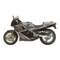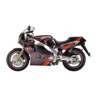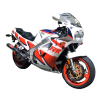
Do you have a question about the Yamaha 1987 FZR1000 and is the answer not in the manual?
| Year | 1987 |
|---|---|
| Manufacturer | Yamaha |
| Model | FZR1000 |
| Compression Ratio | 11.2:1 |
| Transmission | 5-speed |
| Final Drive | Chain |
| Front Tire | 120/70-17 |
| Displacement | 989 cc |
| Bore x Stroke | 75.5 mm x 56.0 mm |
| Maximum Power | 10, 000 rpm |
| Maximum Torque | 8, 500 rpm |
| Fuel System | 4x Mikuni BDST38 carburetors |
| Ignition | TCI (Transistor Controlled Ignition) |
| Front Suspension | Telescopic fork |
| Rear Suspension | adjustable preload and rebound damping |
| Front Brakes | 2 x 298mm discs, 4-piston calipers |
| Rear Brakes | Single disc |
| Seat Height | 780 mm |
| Fuel Capacity | 21 liters |
| Engine Type | Liquid-cooled, 4-stroke, DOHC, 5-valve, inline-four |
Instructions on navigating and understanding the manual's format and symbols.
Details on frame and engine serial number locations and formats for model identification.
A table listing critical torque specifications for various fasteners and components.
Technical specifications related to the motorcycle's chassis components like wheels and suspension.
Lubrication points and lubricant grades for engine components.
Lubrication points and lubricant grades for chassis components.
Detailed diagram illustrating oil flow for specific engine components.
Detailed diagram illustrating oil flow for specific engine components.
Detailed diagram illustrating oil flow for specific engine components.
Explains the purpose and benefits of preventive maintenance procedures.
Exploded view and specifications for the engine's crankshaft assembly.
Exploded view and details for the lower crankcase assembly and related parts.
Exploded view and details for the upper crankcase assembly and related parts.
Exploded view and specifications for the motorcycle's transmission system.
Exploded view and specifications for the clutch assembly.
Exploded view and specifications for the piston and cylinder assembly.
Exploded view and specifications for the cylinder head assembly.
Exploded view and specifications for the camshaft assembly.
Exploded view and specifications for the rear wheel assembly.
Exploded view and specifications for the front brake caliper.
Exploded view and specifications for the rear brake caliper.
Exploded view and specifications for the rear master cylinder.
Exploded view and specifications for the rear shock absorber.
Exploded view and specifications for the swingarm assembly.
Identification and specifications for further electrical system components.
Identification and specifications for additional electrical system components.
