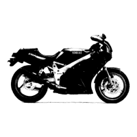
Do you have a question about the Yamaha FZR400 1988-1989 and is the answer not in the manual?
| Bore x Stroke | 56.0 mm x 40.5 mm |
|---|---|
| Cooling System | Liquid-cooled |
| Ignition | CDI |
| Transmission | 6-speed |
| Front Suspension | Telescopic fork |
| Rear Brakes | Single disc |
| Front Tire | 110/70-17 |
| Rear Tire | 140/60-18 |
| Final Drive | Chain |
| Frame | Steel Deltabox |
| Height | 1, 140 mm (44.9 inches) |
| Wheelbase | 1, 375 mm (54.1 inches) |
| Rear Suspension | Monoshock |
| Front Brakes | Dual disc |
| Fuel Capacity | 18 liters (4.8 gallons) |
| Engine Type | Liquid-cooled, 4-stroke, DOHC, inline-four |
Details on vehicle identification number and engine serial number for FZR400 models.
Covers preparation for removal, replacement parts, and handling of gaskets, seals, and O-rings.
Lists and describes specific tools required for tune-up, engine, chassis, and electrical component service.
Provides detailed specifications for engine, lubrication, cooling, fuel, and chassis systems.
Lists maintenance specifications for engine components like cylinder head, camshaft, and cylinder.
Specifies torque values for various parts to be tightened during maintenance and assembly.
Details lubrication points for engine and chassis components with associated symbols.
Covers periodic inspections and adjustments for engine components like valve clearance and carburetor.
Details periodic inspections and adjustments for chassis components like brakes and drive chain.
Step-by-step guide for checking and adjusting the drive chain slack for proper operation.
Instructions for inspecting the brake fluid level and condition.
Procedure for removing the engine and its associated components from the motorcycle.
Detailed steps for disassembling the engine, including cylinder head, camshaft, and pistons.
Covers inspection and repair procedures for engine components like cylinder head, valves, and crankshaft.
Steps for inspecting and installing connecting rods, including lubrication and torque.
Diagram and part numbers for the radiator assembly, fan motor, and related components.
Step-by-step instructions for removing the radiator and associated parts.
Procedures for inspecting the radiator core, hoses, and cap opening pressure.
Diagram and removal steps for the water pump and thermostatic valve assembly.
Exploded view of the carburetor assembly with part numbers and specifications.
Detailed steps for removing the fuel tank, fuel pump, and carburetor assembly.
Instructions for disassembling the carburetor, including float chamber components.
Procedures for adjusting fuel level and pilot screw settings for optimal performance.
Exploded view and specifications for the front wheel assembly.
Step-by-step instructions for removing the front wheel and associated components.
Procedures for inspecting the tire, axle, wheel, and bearings for wear or damage.
Steps for installing the front wheel, including lubrication and balancing.
Guide for finding and adjusting the wheel's heavy spot for proper balance.
Exploded view and specifications for the rear wheel assembly.
Step-by-step instructions for removing the rear wheel and its components.
Procedures for inspecting the rear wheel, axle, bearings, and brake disc.
Steps for installing the rear wheel, including lubrication and chain slack adjustment.
Exploded views and specifications for the front and rear brake systems.
Detailed instructions for replacing the front and rear brake pads.
Steps for disassembling the front and rear brake calipers.
Procedure for disassembling the front and rear brake master cylinders.
Exploded view and specifications for the front fork assembly.
Step-by-step instructions for removing the front fork components.
Detailed steps for disassembling the front fork, including damper rod and inner tube.
Exploded view and removal/installation steps for the handlebar and steering components.
Procedures for inspecting steering head bearings and races for wear or damage.
Exploded views and specifications for the rear shock absorber and swingarm.
Steps for removing the rear shock absorber and its mounting hardware.
Procedures for inspecting the swingarm, bearings, seals, and arms.
Exploded view and inspection steps for the drive chain and sprockets.
Guide for checking and adjusting the drive chain slack.
Wiring diagram illustrating the electrical system of the FZR400U/SUC.
Diagram of various electrical components including switches, relays, and sensors.
Diagram of other electrical components including wiring harness, battery, and ignitor unit.
Procedure for checking switch continuity and terminal connections.
Guide on checking bulb terminals for continuity and condition.
Circuit diagram and description of the digital ignition control system.
Circuit diagram and operation description of the electric starting system.
Circuit diagram for the charging system, including generator and rectifier.
Circuit diagram illustrating the motorcycle's lighting system components.
Circuit diagram detailing the signal system, including turn signals and horn.
Circuit diagram for the cooling system, showing radiator, pump, and thermo switch.
Circuit diagram for the fuel system, including fuel pump and relay.
Circuit diagram for the EXUP system, specific to California models.
Exploded view of the meter assembly, showing speedometer, tachometer, and indicators.
Troubleshooting guide for issues related to starting the engine or hard starting.
Troubleshooting guide for problems related to poor engine idle speed.
Troubleshooting guide for issues affecting engine performance at medium and high speeds.
Troubleshooting guide for problems related to gear shifting or transmission.
Troubleshooting guide for clutch slippage or dragging issues.
Troubleshooting guide for engine overheating or over-cooling issues.
Troubleshooting guide for poor braking effect and related issues.
Troubleshooting guide for oil leaks or malfunctions in the front fork system.
Troubleshooting guide for issues related to unstable motorcycle handling.
Troubleshooting guide for problems with signals, lights, horn, and tachometer.
Guide for adjusting the shock absorber's overall length to change ride height.
Instructions for setting static sag and rider sag by adjusting spring preload.
Explanation of rebound and compression damping adjustments on FOX shocks.
Guidance on experimenting with sag settings for optimal riding style and handling.