Do you have a question about the Yamaha C-2a and is the answer not in the manual?
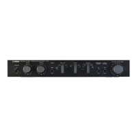
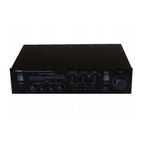
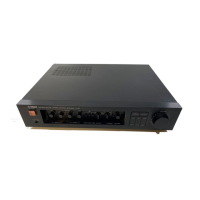
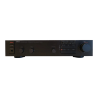
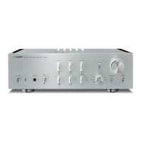
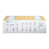
Describes the controls and indicators on the front of the C-2a pre-amplifier.
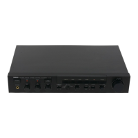
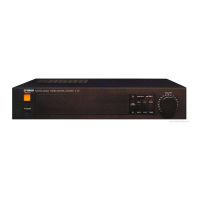
Details the input/output jacks and power connections on the rear of the C-2a pre-amplifier.
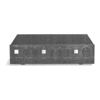
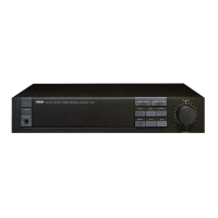
Illustrates and labels component locations when viewing the C-2a pre-amplifier from the top.
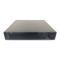
Illustrates and labels component locations when viewing the C-2a pre-amplifier from the bottom.
Explains how to remove the bottom cover of the C-2a pre-amplifier using specific screws.
Outlines the process for removing the main case, including detaching knobs, screws, and connectors.
Describes the steps to remove the MC shield, involving specific screws and side frame manipulation.
Details the procedure for adjusting the power supply voltage to specified levels.
Describes how to check the proper functioning of the muting relays and collector voltage.
Explains how to adjust the MC amplifier section for minimum distortion using an oscillator.
Outlines the process for setting the DC offset for the equalizer section to a specified mV range.
Describes how to adjust the idling current for the equalizer section to a specific mV value.
Details the procedure for adjusting the DC offset of the tone control section with various controls set.
Shows adjustment points and settings for the EQ C. Board, including power supply, offset, and idling current.
Depicts adjustment points and settings for the Tone Control C. Board, covering offset for various controls.
Displays the circuit board layout for the pin jack connections on the C-2a pre-amplifier.
Shows the circuit board layout for the MC Head Amplifier section of the C-2a pre-amplifier.
Presents the circuit board layout for the Equalizer amplifier section of the C-2a pre-amplifier.
Illustrates the circuit board layout for the Tone Control amplifier section of the C-2a pre-amplifier.
Lists and defines the wire color codes used throughout the schematic diagrams of the C-2a pre-amplifier.