Do you have a question about the Yamaha C40TLRZ and is the answer not in the manual?
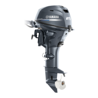
Provides essential specifications for correct outboard motor mounting on the transom.
Covers critical aspects of jet drive engine mounting, maintenance, and shift cable setup.
Provides wiring diagrams for common remote control configurations and engine setups.
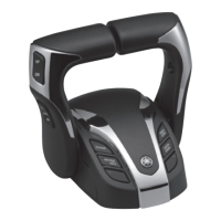
Lists and describes different types of Yamaha remote control boxes, including their part numbers and applications.
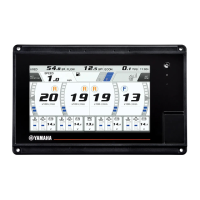
Covers tachometer types, mounting, wiring, and pole setting for optimal performance monitoring.
Discusses Yamaha propeller design principles and available materials like plastic, aluminum, and stainless steel.
Provides detailed charts for selecting the correct propeller based on engine horsepower, pitch, and materials.
Provides comprehensive installation instructions for the 6X1 Dual Station System.
Offers service procedures, troubleshooting, and technical tips for the 6X1 Dual Station System.
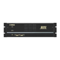
Describes the function of the dual station junction unit for switching controls between stations.
Explains how the actuator uses an electric servo system to perform shifting operations.
Details procedures for checking actuator operation, including cable length adjustments and engine start checks.
Provides a wiring diagram for the first station of a single-engine dual station system.
Offers a wiring diagram for the second station of a single-engine dual station system.
Presents wiring diagrams for the second station of a twin-engine dual station system.
| Power Output | 40 hp |
|---|---|
| Fuel Type | Gasoline |
| Starting System | Manual |
| Cooling System | Water-cooled |
| Gear Ratio | 2.08:1 |
| Cylinders | 3 |
| Fuel System | Carburetor |
| Ignition System | CDI |
| Full Throttle RPM Range | 5000-6000 RPM |
| Fuel Induction System | Reed valve |
| Steering | Tiller |
| Engine Type | 2-stroke |
| Shaft Length | Long (20 in) |
| Fuel Tank Capacity | External tank |
| Alternator Output | 12V 6A |