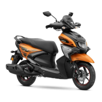
Do you have a question about the Yamaha CYGNUS RAY ZR 2022 and is the answer not in the manual?
| Brand | Yamaha |
|---|---|
| Model | CYGNUS RAY ZR 2022 |
| Category | Motorcycle |
| Language | English |
Purpose of the supplementary service manual.
Defines important notations like WARNING, NOTICE, and TIP, and symbols.
Explains the manual's layout and how to interpret its sections.
Provides definitions for symbols used throughout the manual.
Overview of vehicle features and indicator lights.
Explanation of dashboard indicator lights for disc and drum models.
Details required special tools for maintenance, including part numbers and illustrations.
Provides basic dimensions, weight, and loading information.
Lists engine-related service data, tolerances, and capacities.
Details chassis and suspension specifications, including tire pressure.
Outlines electrical system specifications, including voltage and components.
Specifies torques for standard fasteners and ISO thread pitch.
Torque values for engine and chassis component fasteners.
Illustrates the correct routing of wires and cables throughout the vehicle.
Maintenance intervals and tasks for drum and disc models.
Procedures for checking and adjusting valve clearance, fuel filter, and canister.
Procedures for chassis checks and lubrication, including steering head.
Steps for replacing bulbs and adjusting headlight beam.
Procedures for removing/installing battery, covers, and grab bar.
Steps for removing, checking, and installing the handlebar and its components.
Detailed instructions for rear shock absorber removal, checking, and installation.
Circuit diagrams and troubleshooting for ignition and electric starting systems.
Circuit diagrams and troubleshooting for stop/start, charging, and lighting systems.
Circuit diagrams and troubleshooting for signaling, fuel injection, and fuel pump systems.
Visual identification of electrical components and detailed wiring diagrams.