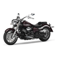
Do you have a question about the Yamaha XV17AS(C) and is the answer not in the manual?
Important notices regarding manual usage and safety precautions.
Key information distinction symbols for warnings and cautions.
Overall specifications for the motorcycle models.
Detailed technical specifications for the engine.
Technical specifications related to the motorcycle chassis.
Technical specifications for the electrical system.
Torque values for assembly and maintenance.
Specific torque values for engine assembly and maintenance.
Specific torque values for chassis assembly and maintenance.
Diagrams and instructions for routing motorcycle cables and wires.
Procedures for recommended checks and adjustments.
Schedule for emission control system maintenance checks.
Comprehensive schedule for vehicle maintenance and lubrication.
Procedures for removing and installing seats and side covers.
Procedures for removing and installing the fuel tank.
Procedures for front wheel and brake disc removal and installation.
Procedures for rear wheel, brake disc, and pulley removal.
Detailed information on front and rear brake systems.
Details on front brake pads, including removal and replacement.
Step-by-step guide for replacing front brake pads.
Procedures for removing and servicing the rear brake master cylinder.
Procedures for front brake caliper removal and disassembly.
Detailed steps for taking apart the front brake calipers.
Guide to inspecting front brake caliper components for wear or damage.
Steps for reassembling and mounting the front brake calipers.
Procedures for removing and installing handlebar components.
Steps for removing and servicing the rear shock absorber and swingarm.
Procedures for drive belt and pulley removal and installation.
Details on rocker arms, push rods, and valve lifters.
Step-by-step guide for installing rocker arms and push rods.
Procedures for installing cylinder head covers.
Exploded view and part list for the clutch assembly.
Instructions for installing the clutch boss nut.
Procedures for removing the generator rotor assembly.
Procedures for crankshaft and connecting rod inspection and installation.
Procedures for inspecting crankshaft and connecting rods for wear.
Step-by-step guide for installing connecting rods onto the crankshaft.
Details on disassembling the main axle assembly of the transmission.
Information related to the motorcycle's carburetor.
Details on the air intake system for the carburetor.
Visual diagrams illustrating the air induction system components.
| Engine Type | Air-cooled, 4-stroke, V-twin, OHV |
|---|---|
| Fuel System | Fuel Injection |
| Ignition | TCI |
| Transmission | 5-speed |
| Front Suspension | Telescopic fork |
| Rear Suspension | Swingarm |
| Displacement | 1670 cc |
| Bore x Stroke | 97.0 mm x 113.0 mm |
| Front Brake | Dual disc |
| Rear Brake | Single disc |
| Seat Height | 690 mm (27.2 in) |


