Do you have a question about the Yamaha DG80-112 and is the answer not in the manual?
Details digital signal processing, presets, reverb, amp output, and speaker.
Outlines MIDI capabilities and lists front/rear panel controls and switches.
Lists all connection jacks and their electrical parameters like impedance.
Covers converters, sampling frequency, input/output levels, and impedance.
Details power requirements, consumption, unit dimensions, and weight.
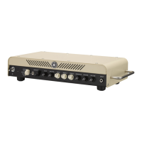
Identifies and explains each control, display, and switch on the front panel.
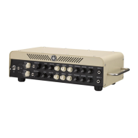
Identifies and explains each connector and control located on the rear panel.
Visual guide to the physical arrangement of components on key circuit boards.
Illustrates the overall signal path and functional blocks of the amplifier system.
Covers removing the pre-main unit, speaker, and front panel assembly.
Details the process for removing specific circuit boards like DM, ANR, and Main.
Specific instructions for safely replacing the internal backup battery.
Details pin assignments and functions for the main CPU and related integrated circuits.
Visual block diagrams for various logic, memory, and DSP integrated circuits.
Block diagrams for operational amplifiers, motor drivers, and other specialized ICs.
Instructions on how to access and prepare the unit for self-testing.
Outlines steps for performing functional tests like switch, LED, and memory checks.
Details audio output verification and necessary calibration procedures.
Explains common error messages, their causes, and corrective actions.
Comprehensive chart of supported MIDI messages, functions, and modes.
Visual representation of the DM circuit board and its component placement.
Visual layouts for the PN and VR circuit boards, showing component placement.
Visual layouts for the Main, ANF, ANF2, and ANR circuit boards.
Comprehensive list of parts for the entire unit assembly.
Specific parts list detailing components for the pre-main unit.
Parts list for the front panel assembly, including controls and indicators.
Parts list detailing components for the chassis assembly.
Parts list for the overall cabinet assembly, including enclosure and mounting hardware.
Detailed list of all electronic components with part numbers and specifications.
Detailed schematic diagram for the DM and ANR sections of the amplifier.
Detailed schematic diagram for Main, PN, VR, ANF, and ANF2 sections.
| Power Output | 80W |
|---|---|
| Speaker Size | 12 inches |
| Channels | 2 |
| Amplifier Type | Solid State |
| Reverb | Yes |
| Effects | Chorus, Flanger, Phaser, Tremolo |
| Inputs | 1x Instrument, 1x Footswitch |