Do you have a question about the Yamaha DX7 II FD and is the answer not in the manual?
| Type | Digital Synthesizer |
|---|---|
| Polyphony | 16 Voices |
| Sound Engine | FM Synthesis |
| Synthesis Type | FM (Frequency Modulation) |
| Oscillators | 6 Operators |
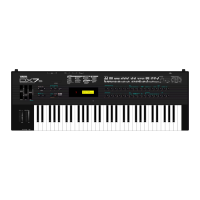
| Keyboard | 61 Keys |
| Velocity Sensitivity | Yes |
| Aftertouch | Yes |
| Display | LCD |
| MIDI | In, Out, Thru |
| Year Released | 1987 |
| Effects | Chorus, Reverb |
| Storage | Internal Memory |
| Controls | Buttons |
| Outputs | Stereo, Headphones |
| Dimensions | 4.6 inches |
| LFO | 1 LFO |
Technical details of the 61-key keyboard with touch response.
FM tone generator specs: 6 operators, 32 algorithms.
Note output priority and voice allocation details.
Lists physical controls like sliders, wheels, and switches.
Connectors for external devices like foot switches.
Internal, ROM, and external memory configurations.
Specs for the built-in 3.5" micro floppy disk drive.
Details of the LC display and LED indicators.
Physical size, weight, power supply voltage, and consumption.
Lists standard and optional accessories.
Instructions for removing the FDD assembly from the DX7II-FD model.
Procedure for safely removing the keyboard from the synthesizer.
Steps to remove PNA, PNB boards, and LCD/LED display.
Guide for removing the wheel assembly and headphone circuit board.
Explains error messages related to disk read/write, protection, and file system issues.
Details error messages concerning MIDI data reception and buffer issues.
Details on channel voice, control change, program change, and other MIDI transmission data.
Specifies the requirements for receiving various MIDI messages and data types.
Information on poly/all note off and mono/all note off MIDI channel modes.
Explains system exclusive messages for parameter changes, bulk data, and dumps.
Pin details for the YM2604 OPSII chip, including functions and data buses.
Pin details for the YM3609 Envelope Generator, covering power and data pins.
Pinout and functions for the PCM54HP DAC chip.
Pinout and functions for the WD1772PH-02 FDC chip.
Pinout and functions for the μPD8255AC-2 I/O port controller.
Pinout details for various connectors (CN1-CN14) used in the DM circuit.
Layout diagrams for the PNA and PNB circuit boards, detailing component placement.
Layout diagram for the HP circuit board, showing components and connector pinouts.
Layout diagram for AD circuit boards (USA model), including connector pinouts.
Layout diagram for AD circuit boards (Canadian model) and component details.
Layout diagram for AD circuit boards (West German model).
Further details on parts, including resistor/capacitor values and specifications.
List of parts used in the overall assembly, including part numbers and descriptions.