1-8
MOUNTING THE OUTBOARD
MOTOR
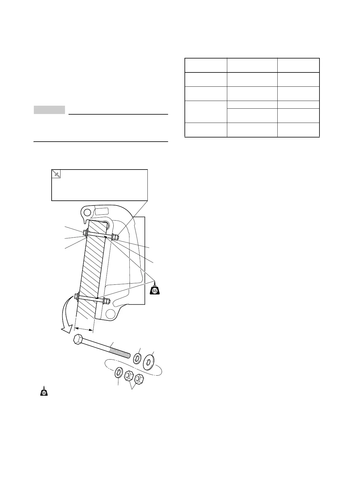
4. Apply a sealant to the mount holes, and se-
cure the motor with supplied mount hard-
ware.
For tightening procedure, first tighten the in-
side nut, then the double nuts each other.
NOTICE
Make sure there is no clearance between
boat transom and motor clamp bracket.
Otherwise, the clamp bracket could break.
* The upper mount bolt is usually installed to
the 2nd hole from top.
* Tighten the mounting bolts/ nuts by suitable torque
due to boat transom structure, material, design,
etc.
For 115 – 300 and F115 – F350, select the
transom mount bolt due to the boat transom
thickness.
* High tension bolt is recommended to F300/F350.
(a)
For reference:
(a)
(b)
(b)
(d)
(d)
(b)
(b)
(c)
(c)
(a) Mounting bolt
(b) Small washer
(c) Large washer
(d) Nut
: Sealant
T
M8: 18 Nm, 1.8 kgf•m, 13 lb•ft
M10: 36 Nm, 3.6 kgf•m, 27 lb•ft
M12: 52 Nm, 5.2 kgf•m, 38 lb•ft
Boat transom
thickness (T)
Mount bolt size Bolt P/N
55 – 65 mm
(2.17 – 2.56 in.)
M12 ×115 mm 90101-12M03
65 – 75 mm
(2.56 – 2.95 in.)
M12 ×130 mm 90101-12M05
75 – 95 mm
(2.95 – 3.74 in.)
M12 ×150 mm 90101-12M77
M12 ×150 mm
[High tension bolt]
90101-12031
95 – 115 mm
(3.74 – 4.53 in.)
M12 ×170 mm
[High tension bolt]
90101-12036
 Loading...


