Do you have a question about the Yamaha GE-3 and is the answer not in the manual?
Detailed safety guidelines for operating the GE-3, including warnings about water, heat, power sources, and servicing.
Explanation of warning symbols like lightning flash with arrowhead and exclamation point used in the manual.
Important notes before connecting the GE-3 to other components, ensuring power is off and wires are secure.
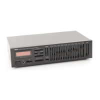
Caution regarding placing the GE-3 in an audio rack with other components, using provided rubber feet.
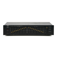
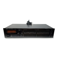
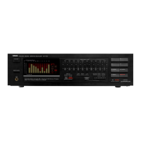
Description of the power switch and the 10-band equalizer levers for frequency adjustment on both channels.
Explanation of the ATT control, EQUALIZER switch, EQ REC switch, and TAPE MONI switch functions.
Diagram illustrating the signal flow and operation of the various switches on the GE-3.
Steps for adjusting the GE-3 to achieve desired sound coloration for records and FM broadcasts.
Procedure for equalizing playback from a tape deck using the GE-3.
Instructions on how to equalize signals when recording to a tape deck.
Discusses using the GE-3 for reducing tape hiss, compensating room acoustics, and enhancing car stereo sound.
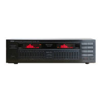
The Yamaha GE-3 is a Natural Sound Stereo Graphic Equalizer designed to enhance and customize the audio experience. It features 10 frequency bands for both left and right channels, allowing for precise control over the sound spectrum. The device also includes an attenuator control, equalization of recordings, and a tape monitor function, making it a versatile addition to any audio system.
The primary function of the GE-3 is to provide detailed control over audio frequencies. With 10 frequency bands per channel (32 Hz, 64 Hz, 125 Hz, 250 Hz, 500 Hz, 1 kHz, 2 kHz, 4 kHz, 8 kHz, and 16 kHz), users can adjust the sound by ±10 dB for each band. This allows for fine-tuning the audio output to compensate for room acoustics, emphasize preferred frequencies, or improve the sound quality of recordings.
The equalizer's levers are designed to be intuitive. For instance, the 32 Hz lever boosts low-frequency sounds like bass violins or pipe organs when slid up, and reduces unpleasant low-frequency noise such as rumble or hum when slid down. Similarly, the 64 Hz and 125 Hz levers adjust bass sounds from instruments and drums. The 250 Hz lever emphasizes medium-low frequencies, useful for acoustic guitars, while the 500 Hz lever is mainly for adjusting vocal levels, adding depth and richness.
Higher frequency bands also offer distinct controls. The 1 kHz lever enhances vocal presence when raised and de-emphasizes vocals when lowered. The 2 kHz lever controls both vocals and brass sounds, increasing brightness and brilliance when set higher, and making them more mellow when set lower. The 4 kHz lever enhances high-frequency echo sounds from vocals and string instruments, and is particularly effective for controlling violin sounds. The 8 kHz lever emphasizes high frequencies for increased fidelity, while lowering it reduces sharpness. Finally, the 16 kHz lever controls overall sound presence, emphasizing high-frequency sounds like cymbals when raised, and reducing tape hiss or other high-frequency noise when lowered.
The attenuator control (ATT) is crucial when equalizer levers are set to high levels or when the EQUALIZER switch is ON, as these actions can increase the overall volume. The ATT control helps maintain the equalized signal while reducing the volume to the EQUALIZER OFF level, preventing distortion from high-level input signals.
The EQUALIZER switch activates or deactivates the equalizer effect. When pressed ON, the frequency modifications take effect; when turned OFF, equalization is terminated. The EQ REC switch allows for equalizer recording. When this switch is ON, the output to the tape deck is equalized and recorded in the equalized mode. If OFF, an unequalized output is sent to the tape deck. The TAPE MONI switch enables monitoring of a tape deck connected to the GE-3, even during recording. When OFF, other music sources connected to the amplifier (e.g., AM/FM tuner, turntable) are played.
The GE-3 is designed for seamless integration into an existing audio system. Before connecting, it is essential to ensure all power switches are OFF and to connect all wires securely to the proper terminals (R to R, L to L). Improper connections can lead to static or other sound quality issues. To prevent line noise, input/output cords should not be tied with the power cord or put under tension.
The manual provides clear instructions for various operations:
One practical application is the reduction of tape hiss. Since tape hiss is in the high-frequency range, it can be reduced by setting the 4 kHz to 16 kHz control levers at +4 dB during recording, and then lowering them to -4 dB during playback. This brings the frequency response back to "0" while eliminating the hiss.
The GE-3 also helps in compensating for room acoustics. Factors like speaker characteristics, furniture, wall materials, and rugs can affect tonal response. By adjusting the equalizer levels for both channels, users can compensate for these factors and significantly improve sound quality.
Furthermore, the equalizer allows for emphasizing preferred frequencies. Whether a user prefers more bass, vocal definition, or overall clarity and brightness, the GE-3 offers the flexibility to tailor the system's sound to individual preferences. It can also improve the sound of car stereo systems, which often emphasize midranges at the expense of lowest and highest frequencies, by adjusting bass and treble levels.
To ensure optimum performance and longevity, several maintenance guidelines are provided:
By following these guidelines, users can ensure the safe and effective operation of their Yamaha GE-3 stereo graphic equalizer, enjoying its benefits for years to come.
| center frequency | 32, 64, 125, 250, 500 Hz, 1, 2, 4, 8, 16 kHz |
|---|---|
| harmonic distortion | Less than 0.005% |
| power supply | AC 110/120/220/240 V, 50/60 Hz |
|---|---|
| power consumption | Not specified |
| input sensitivity/impedance | 150 mV/47 kΩ |
|---|---|
| maximum output | Better than 6 V |
| signal-to-noise ratio | Better than 92 dB |
| frequency response | 10 to 35, 000 Hz, ±0.5 dB |
|---|---|
| dimensions | 435 x 91 x 227 mm (17-1/8" x 3-5/8" x 9") |
| weight | 2.8 kg (6 lbs. 3 oz.) |