Do you have a question about the Yamaha GEP50 and is the answer not in the manual?
Keep the unit away from extreme temperatures, humidity, dust, and vibration.
Handle the unit with care to prevent damage from physical impacts.
Do not open the case; refer all servicing to qualified YAMAHA personnel.
Turn power OFF before connecting or disconnecting cables to prevent damage.
Always grip connectors, not cords, when plugging/unplugging cables.
Clean the unit only with a soft, dry cloth; avoid solvents.
Ensure the unit's power supply voltage matches the local AC mains supply.
Keep the GEP50 away from TVs/radios to prevent interference.
Contains a lithium battery for memory retention; replace by qualified personnel.
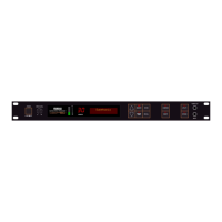
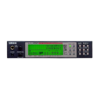
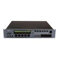
Details the controls and indicators on the front panel of the GEP50.
Controls unit power ON/OFF.
Adjusts input signal level with the INPUT LEVEL meter.
Seven LEDs indicating input signal level from -30 dB to 0 dB.
Shows the number of the currently selected memory location.
Displays effect titles, parameters, values, and messages.
Activates memory selection mode for choosing effect locations.
Accesses and cycles through effect parameters for editing.
Used to select memory locations or change parameter values.
Stores edited effect parameters into user memory locations.
Activates the selected effect memory location.
Compares edited parameter sound with the original.
Activates the INSERT loop for external signal processors.
Accesses utility functions like title editing and MIDI control.
Switches the selected effect ON or OFF.
Output jack for connecting a guitar tuner.
Connects guitar or other audio source to the GEP50.
Details the rear panel connections and jacks.
Receives MIDI signals for remote effect selection and control.
Relays MIDI data received at MIDI IN to other devices.
Connects a footswitch for foot control of the BYPASS function.
Connects a footswitch for sequential memory recall.
Provide stereo output signal to amplification or mixing equipment.
Allow connection of an external signal processor into the effect chain.
Rear panel input jack duplicating front panel function.
Describes the 100 internal memory locations, ROM and RAM.
Explains how to select and recall effect programs using buttons.
Compares edited parameter sound with the original during editing.
Details the process of saving edited effect programs to user memory.
Describes common BALANCE and OUT LVL parameters found in all effects.
Function to create original titles for edited effect programs.
Sets up GEP50 to select programs via external MIDI control.
Guides through selecting MIDI banks and setting receive channels.
Links MIDI program change numbers to GEP50 memory locations.
Sets the range of memory locations selectable via footswitch.
Outlines how the GEP50 receives MIDI signals.
Details the types of MIDI data received and their functions.
Covers NOTE ON/OFF messages and their effect on GEP50 functions.
Explains how PROGRAM CHANGE messages select GEP50 effects.
Lists electrical specifications like frequency response and dynamic range.
Details input specifications, channels, level, and impedance.
Provides details on analog-to-digital and digital-to-analog conversion.
Lists output specifications, channels, level, and impedance.
Specifies ROM and RAM memory capacity for presets and user data.
Details MIDI control functions like program number and note ON/OFF.
Lists front panel controls, display, and jacks.
Lists rear panel jacks and MIDI terminals.
Specifies MIDI IN/OUT/THRU connections.
Covers general specifications like power, dimensions, and weight.
| Brand | Yamaha |
|---|---|
| Model | GEP50 |
| Category | Recording Equipment |
| Language | English |