Do you have a question about the Yamaha MS101III and is the answer not in the manual?
| Product color | Black |
|---|---|
| Volume control | Rotary |
| Housing material | - |
| Recommended usage | PC |
| Suitable for outdoor use | No |
| Driver diameter | 100 mm |
| Number of drivers | 1 |
| Speaker placement | Tabletop/bookshelf |
| Audio output channels | 1.0 channels |
| Impedance | - Ω |
| Frequency range | 75 - 18000 Hz |
| RMS rated power | 10 W |
| Quick installation guide | Yes |
| Connectivity technology | Wired |
| Power source type | AC |
| Power consumption (typical) | 30 W |
| Depth | 192 mm |
|---|---|
| Width | 147 mm |
| Height | 214 mm |
| Weight | 2500 g |
Covers warnings about service, static discharge, chemical content, and handling precautions.
Specific instructions for wiring the mains lead for UK users.
Details type, frequency range, SPL, dimensions, and weight of the speaker.
Covers speaker unit, sensitivity, impedance, and amplifier performance metrics.
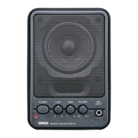
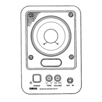
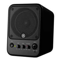
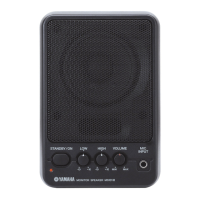
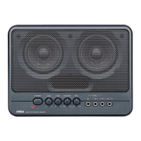
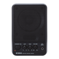
Identifies all controls and input/output jacks on the front panel.
Identifies input/output jacks and other connections on the rear panel.
Provides detailed external measurements of the speaker unit in mm and inches.
Illustrates the physical arrangement of circuit boards (MA1/3, MA2/3, MA3/3).
Shows the functional blocks and signal path of the audio system.
Step-by-step guide to removing the speaker baffle and rear assembly.
Instructions for removing circuit boards (MA1/3) and the speaker unit.
Procedures for removing MA2/3, MA3/3 boards, power transformer, and AC cord.
Pinout and functional description for μPC4570HA-A ICs.
Pinout and functional description for LA4490N power amplifier IC.
Detailed schematic of the MA1/3 circuit board with component layout.
Detailed schematic of the MA2/3 circuit board with component layout.
Detailed schematic of the MA3/3 circuit board with component layout.
Specifies voltage, load, and input conditions for product testing.
Lists key performance metrics like output power, sensitivity, and noise.
Default positions for STANDBY/ON, LOW, HIGH, and VOLUME controls.
Checks for smooth operation and sound quality during use.
Exploded view and list of major service parts for the unit.
Comprehensive list of electrical parts with part numbers and descriptions.
Complete circuit diagram showing interconnections of all major components.