Do you have a question about the Yamaha P7000 and is the answer not in the manual?
Essential warnings about electrical hazards, lightning, and modifications.
Guidelines for safe installation, placement, and ventilation.
Precautions for safe usage, handling cables, and environmental factors.
Cautions regarding operating environment, moisture, heat, and instability.
Explains XLR connector pinout for grounding, plus, and minus signals.
Advice on potential interference from mobile phones near the device.
Warning against modifying the device to maintain FCC compliance.
Requirement to use high-quality shielded cables for connections.
Overview of the amplifier's main functions and capabilities.
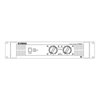
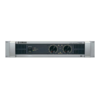
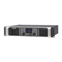
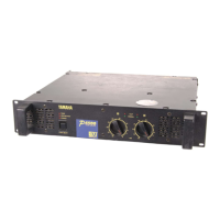
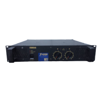
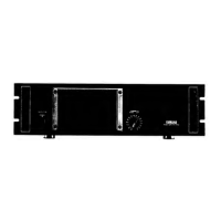
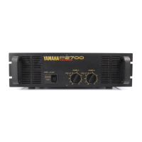
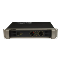
Description of controls and indicators on the amplifier's front panel.
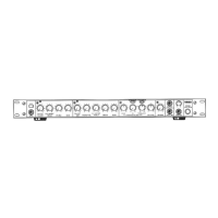
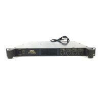
Description of connectors and switches on the amplifier's rear panel.
Minimum impedance requirements for connected speakers.
Instructions on how to properly connect speaker cables.
Detailed technical specifications for the amplifier models.
Schematic overview of the amplifier's internal signal flow.
Physical dimensions of the amplifier unit.
Graphs illustrating amplifier performance characteristics.
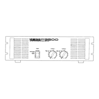
Controls the unit's power and indicates operational status.
Indicates when the heatsink reaches a high temperature.
Shows when the protection circuit is activated.
Signals signal distortion exceeding 1%.
Indicates when an output signal is present.
Adjusts the audio output volume for each channel.
Indicates when the YS Processing feature is active.
Ventilation openings for cooling the amplifier.
Selects filter type (SUBWOOFER/LOW CUT) and sets cutoff frequency.
Activates low-frequency correction for improved sound.
Provides XLR and TRS input options for audio signals.
Selects the amplifier's operational mode.
Provides Neutrik Speakon, clamp, and headphone outputs.
Ground terminal for noise reduction.
Connection diagrams for STEREO and PARALLEL modes.
Connection diagrams for BRIDGE mode.
Instructions for connecting speaker wires using clamp terminals.
How to connect and secure Neutrik NL4FC Speakon connectors.
Procedure for connecting headphones to the rear panel jack.
Guidelines for installing multiple units in an EIA rack.
Using blank panels for proper airflow in rack installations.
Detailed performance and electrical specifications for each model.
List of controls and indicators on the front panel.
Description of rear panel connectors and switches.
Explanation of front panel indicator functions.
Details on amplifier protection circuits.
Specifications for power voltage and frequency.
Physical measurements of the amplifier unit.
Graphs illustrating power consumption vs. output power.
Diagnosing issues based on indicator lights (CLIP, TEMP, PROTECTION).
Resolving issues when the unit's power turns off unexpectedly.