EasyManua.ls Logo

Yamaha P2250 User Manual

Yamaha P2250
44 pages
To Next Page IconTo Next Page
Page #1 background imageLoading...
Page #1 background image

Other manuals for Yamaha P2250

Question and Answer IconNeed help?

Do you have a question about the Yamaha P2250 and is the answer not in the manual?

Yamaha P2250 Specifications

General IconGeneral
BrandYamaha
ModelP2250
CategoryAmplifier
LanguageEnglish

Summary

How to Use This Manual

Introduction to Yamaha Power Amplifiers

Model Overview and Features

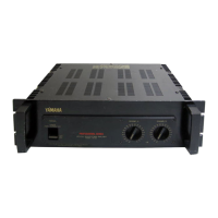
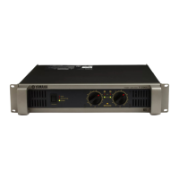
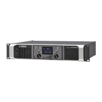
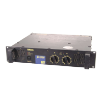
Describes the P1150, P1250, P2150, P2250, their features, and internal circuitry.

Brief Operating Instructions

Front Panel Controls

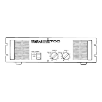
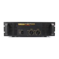
Details the front panel controls and indicators for P1150/P1250 and P2150/P2250 models.

Input Level Controls and Indicators

Explains the function of input attenuators and signal/clip LEDs.

Brief Operating Instructions Continued

Power Switch and Protection Indicators

Describes the power switch operation and protection circuit indicators.

Cooling System and Filter Maintenance

Explains the cooling fan operation and how to clean the air filter.

Rear Panel Connectivity

Input Connectors Explained

Details the XLR and phone jack inputs, including wiring conventions.

MONO/STEREO Mode Switch

Explains how to select between stereo and bridged mono operation modes.

Output Connections and Protection

Standard Speaker Output Connections

Illustrates normal speaker connections using binding posts and phone jacks.

Fuse Specifications and Purpose

Lists fuse ratings for each model and explains their protective function.

Amplifier Operation Procedure

Step-by-Step Setup Guide

Provides a sequence for turning on and setting up the amplifier and system.

AC Power Source Precautions

Advises on ensuring adequate AC power capacity and safe usage.

Installation and Input Connections

Input Connector Details

Detailed explanation of XLR and phone jack inputs and wiring.

Daisy-Chaining Amplifiers

Shows how to connect multiple units for signal distribution.

Output Connections

Stereo Mode Output Wiring

Diagrams illustrating normal stereo mode speaker connections for P2150/P2250.

Bridged MONO Operation

MONO Mode Wiring Diagram

Illustrates speaker connections for P2150/P2250 in bridged mono mode.

Safety Cautions for Bridged Operation

Highlights critical safety warnings when using bridged mono mode.

Sound System Wiring Information

Balanced vs. Unbalanced Wiring

Explains the principles and differences between balanced and unbalanced audio cables.

Input Transformers in Audio Systems

Signal Cable Considerations

Cable Length and Impedance Effects

Discusses how cable length and impedance impact signal quality and noise.

Standard Audio Signal Levels

Defines mic level, line level, and speaker level signal ranges.

Dynamic Range and Headroom Concepts

Setting System Audio Levels

General Level Adjustment Approach

Provides a systematic method for setting audio levels for optimal performance.

Selecting Headroom and Adjusting Levels

Guides on choosing headroom and adjusting gain structure for music reproduction.

Grounding Principles and Safety

Understanding and Avoiding Ground Loops

Ground Loop Mitigation Techniques

Grounding Safety and Noise Minimization

Offers suggestions for minimizing safety conflicts and noise from ground loops.

AC Outlet Wiring and Safety

Safety Grounding with 2-Wire Outlets

Explains how to adapt 2-wire outlets for safe grounding of 3-wire plugs.

Common AC Outlet Wiring Faults

Describes improperly wired outlets like lifted grounds and neutrals.

AC Safety Best Practices

Speaker Wiring Guidelines

Selecting Appropriate Speaker Wire

Recommends wire gauge, type, and stranded wire for speaker connections.

Calculating Speaker Load Impedance

Explains how to calculate the total impedance of speaker loads.

Speaker Wiring Configurations

Series and Parallel Wiring Examples

Illustrates impedance and power distribution for series and parallel speaker wiring.

Speaker Wiring Techniques

Series/Parallel Wiring for Multiple Speakers

Covers series/parallel combinations and notes on impedance and speaker failure.

Distributed Speaker Systems

Constant Voltage System Description

Introduces constant voltage systems and their application in distributed audio.

Speaker Transformer Information

Calculating Bridged Mono Power Output

Multi-Amplified Speaker Systems

Crossover Network Functions

Crossover Network Types

Low-Level vs. High-Level Crossovers

Compares low-level (electronic) and high-level (passive) crossover networks.

Speaker System Crossover Examples

Amplifier Power Rating Methods

Peak Power Definition

Explains peak power as maximum undistorted output for transient signals.

RMS Power Explained

Defines continuous average sine wave power, formerly known as RMS power.

Dynamic Headroom Measurement

Describes IHF's dynamic headroom rating for music power.

Speaker Protection Mechanisms

Output Relay Protection

Details the output relay that prevents turn-on thumps and DC faults.

Current Limiting Circuitry

Explains current limiting to prevent overload from shorts or low impedance.

Speaker Fuse Considerations

Discusses the use and limitations of fuses for speaker protection.

Signal Processing for Speaker Protection

Compressor/Limiter Functions

Explains how compressors/limiters prevent clipping and protect drivers.

Equalizers and Filters for Power Management

Discusses using EQ and filters to reduce unnecessary power dissipation.

High Frequency Driver Protection

Details protection networks, like capacitors, for high frequency drivers.

High Pass Filter Design for Driver Protection

Specifications - P1150

Specifications - P1250

Specifications - P2150

Specifications - P2250

Block Diagram

Performance Graphs

Dimensions

Service Information

Related product manuals