Do you have a question about the Yamaha P2160 and is the answer not in the manual?
Keep unit away from extreme temperatures, humidity, dust, and vibration to prevent damage.
Handle the unit with care to prevent damage from strong physical shocks.
Do not open the case or attempt repairs; refer to qualified personnel to avoid voiding the warranty.
Always turn the power off before connecting or disconnecting cables to prevent equipment damage.
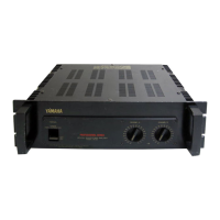
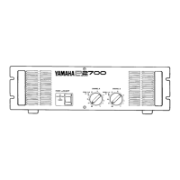
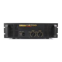
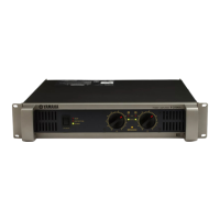
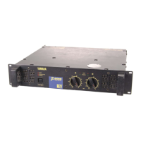
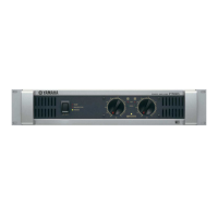
LED indicators for protection circuit status, signal presence, and output clipping.
Button to turn the unit on/off, with an indicator light.
Controls for input sensitivity adjustment and preventing accidental resetting of levels.
Balanced XLR-3-31 type input connectors for audio signals.
1/4-inch TRS phone connectors for balanced/unbalanced input signals.
Terminals for connecting speakers, with red for positive and black for negative.
Rear panel switch to select between stereo and monaural (BTL) operation.
Set the rear panel MODE switch to MONO for monaural operation.
Connect channel A input and specific speaker terminals for BTL monaural setup.
Install blank panels and fans for cooling; ensure 100mm rear space and good location.
Ensure amplifier heat does not affect other rack components when mounting with other equipment.
Specifications for the fan unit, including volume (29 CFM) and pressure (5 mm H2O).
Details on Yamaha VP1 ventilation panel, requiring at least 35% open area.
Recommends fan cooling for rack installations to prevent damage from overheating; specifies minimum airflow.
Guidelines for mounting in portable racks (road cases), including ventilation holes.
Place housed amplifiers to ensure ventilation paths are not blocked.
Screw holes are provided in the rear for amplifier support; refer to dimensions for positions.
Steps include turning power off, removing covers, feeding wires, and reattaching covers.
Use heavy gauge cables and speaker systems with sufficient power handling for high output.
Connect an in-line fuse to protect speakers if their power handling is lower than the amplifier's output.
Details on power output levels for stereo/mono and frequency response characteristics.
Specifications for Total Harmonic Distortion (THD), Intermodulation Distortion (IMD), and residual noise.
Includes damping factor, slew rate, sensitivity, voltage gain, and input impedance.
Description of indicator LEDs and protection circuit trigger points.
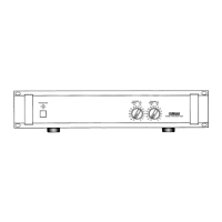
Detailed measurements of the amplifier unit in millimeters and inches.
Specifies the total weight of the amplifier unit.
Graph illustrating frequency response for stereo mode with 8-ohm load.
Graphs showing Total Harmonic Distortion against output power for different load impedances.
Graphs showing Total Harmonic Distortion against frequency for various output power levels.
Graph detailing power consumption relative to output power in stereo mode.
Addresses causes for CLIP indicator lights, such as shorts or excessive load, and remedies.
Covers causes for PROTECTION indicator lights like overheating or DC voltage, and their remedies.
Diagram showing signal paths, input/output stages, and protection circuit integrations.
Illustrates the power supply circuit, switch, and LED driver logic for indicators.
Information on Yamaha's global network of factory-trained service personnel for support.