Do you have a question about the Yamaha P2150 and is the answer not in the manual?
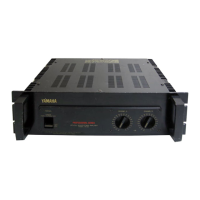
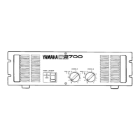
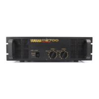
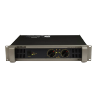
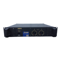
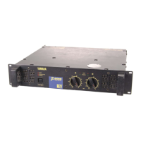
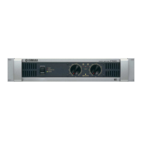
Describes the front panel controls and indicators for P1150/P1250 and P2150/P2250 models.
Details the function and design of the input attenuator controls for accuracy.
Explains the meaning and function of the Signal and Clip LEDs.
Explains the operation of the power switch and protection indicators.
Details the amplifier's cooling system and filter maintenance.
Describes the input connectors (XLR and phone jacks) and their wiring.
Explains the function of the rear panel mode switch for P2150/P2250.
Details the speaker output connections (phone jacks and binding posts).
Explains the purpose and rating of the amplifier's fuse.
Advises on safe AC power sourcing and distribution for amplifiers.
Details XLR and phone jack input configurations and daisy-chaining.
Describes speaker output connections and load impedance requirements.
Explains the principles and differences between balanced and unbalanced signal wiring.
Discusses the applications and benefits of using input transformers.
Defines and categorizes standard audio signal levels (Mic, Line, Speaker).
Explains system dynamic range and the concept of headroom.
Provides a general guide to optimizing system component levels.
Guides on selecting headroom and adjusting system levels for optimal performance.
Crucial warning about electrical codes and liability during installation.
Explains what ground loops are, why they cause noise, and how to avoid them.
Discusses balanced lines and ground lift switches for noise reduction.
Caution regarding microphone grounding and potential shock hazards.
Explains how AC outlet wiring affects grounding and overall safety.
Instructions for safely grounding equipment using 2-wire outlets.
Explains issues with lifted grounds in AC outlets.
Discusses problems caused by lifted neutral connections in AC outlets.
Provides practical safety tips for working with AC power outlets.
Guidance on selecting the correct wire gauge and type for speaker cables.
Explains how to calculate impedance for series and parallel speaker configurations.
Diagrams illustrating speaker wiring configurations and their resulting impedances.
Introduces distributed speaker systems and constant voltage wiring.
Provides details on line transformers used in distributed speaker systems.
Explains the differences between low-level and high-level crossover networks.
Discusses the advantages and disadvantages of low-level and high-level crossovers.
Explains the Continuous Average Sine Wave power rating.
Defines IHF Power and Dynamic Headroom specifications.
Describes the function of the output relay for turn-on protection.
Explains the current limiting circuitry for amplifier overload protection.
Discusses the use and selection of fuses for speaker protection.
Explains the function and use of compressor/limiters.
Details protection networks for high-frequency drivers.
Explains the use of equalizers and filters for sound optimization.
Provides detailed stereo operation specifications for the P2150 model.
Provides detailed bridged mono operation specifications for the P2150 model.
Provides detailed stereo operation specifications for the P2250 model.
Provides detailed bridged mono operation specifications for the P2250 model.
Graphs showing Total Harmonic Distortion vs. output power for P2150.
Graphs showing Total Harmonic Distortion vs. frequency for P2150.
Graphs showing Total Harmonic Distortion vs. output power for P2250.
Graphs showing Total Harmonic Distortion vs. frequency for P2250.
Graph showing damping factor versus frequency for the P2250.
Graph showing frequency response characteristics for all models.