Do you have a question about the Yamaha P2050 and is the answer not in the manual?
Overview of the P2050 amplifier's capabilities and manual content.
Explains the structure and content of each section of the manual.
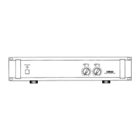
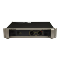
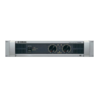
Details on Power Indicator, Power Switch, and Input Attenuators.
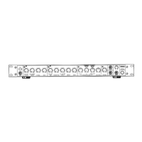
Covers input/output connectors, mode switches, filters, and AC power.
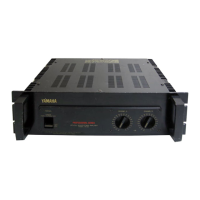
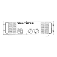
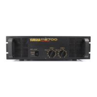
P2050 as a versatile, high-quality audio power amplifier.
Details on log-linear, 22-step, dB-calibrated input attenuators.
XLR and phone jack inputs, binding post outputs.
Conversion to a higher power mono amplifier configuration.
Describes sound quality, distortion, damping factor, and frequency response.
Chassis construction, cooling, protection circuits, and reliability.
Power output, frequency response, THD, IMD, input sensitivity, impedance, damping, hum/noise, rise time, slew rate, separation, phase, offset.
Thermal protection, protection circuits, turn-on/off, AC power, efficiency.
Connectors, indicators, controls, fuse, dimensions, weight, color.
95 watts continuous average sine wave power into 16 ohms.
+0dB, -1dB, 20Hz to 50kHz.
Less than 0.01% @ 50 watts into 16 ohms at 1kHz.
Less than 0.05% at 50 watts into 16 ohms.
OdB (0.775V) produces 95 watts into 16 ohms.
25 kohms minimum (unbalanced).
Greater than 200 at any frequency from 20Hz to 1kHz.
At least 110dB signal-to-noise ratio.
25 volts per microsecond, or better.
Discusses power bandwidth, frequency response, THD, damping factor, and impedance.
Discusses output power vs. load impedance and THD vs. power/frequency.
Graphs showing crosstalk and phase response.
Graphs of output power vs. consumption/efficiency and mono power bandwidth.
Graphs showing THD vs. power and frequency in mono mode.
20kHz and 1kHz square wave responses showing waveform accuracy.
10Hz square wave response and response into inductive loads.
1kHz and 20kHz sine wave response with noise and distortion components.
Response to DC input, showing protection against voltage fluctuations.
Detailed explanation of various distortion types and their causes.
Discusses flat response, subsonic limitation, and filter switch functions.
Covers unit step response, power bandwidth, phase, and channel separation.
Covers hum/noise, rise time, slew rate, input impedance, sensitivity, and gain.
Details protection circuits and thermal characteristics.
Explains back EMF and its role in damping loudspeaker cone motion.
Discusses impedance differences between pro and hi-fi equipment.
How to connect pro gear to hi-fi gear and vice versa.
Details nominal professional and hi-fi line levels.
Explains dynamic range, noise floor, and headroom in audio systems.
Illustrates signal flow and levels from microphone to speakers.
Explains how gain overlap provides headroom adjustment.
How input sensitivity is specified (OdB vs. peak OdB).
Benefits of pro gear like balanced lines, low impedance, high levels.
Covers shelf and rack mounting options for the P2050.
Details on using cooling fans and bracing for road cases.
Discusses matching, bridging inputs, and terminating resistors.
Covers attenuation pads and their values for different circuits.
How to construct a box for impedance matching transformers.
How to construct a box for voltage step-up transformers.
Lists manufacturers for matching and step-up transformers.
How to build a box for bridging transformers.
Diagram for constructing a bridging transformer box.
Discusses P2050's 25k-ohm impedance and load effects.
How to set signal levels for optimal dynamic range and headroom.
Step-by-step guide for setting system headroom.
Classifies audio circuits by signal level and routing guidelines.
Discusses shielded cable for balanced and unbalanced signals.
Recommends phone, XLR, and banana connectors for audio.
Step-by-step guide for wiring RCA plugs.
Detailed steps for wiring male XLR connectors.
Detailed steps for wiring female XLR connectors.
Guide for wiring 2-conductor phone plugs.
Guide for wiring 3-conductor phone plugs.
Explains the function of the unbalanced input polarity switch.
How the P2050 acts as a voltage source and load impedance effects.
Details fuse, grounding, thermal protection, and overload protection.
Defines terms like ground, earth, common, shield, and ground loop.
Explains how ground loops cause noise and how to avoid them.
Method to avoid ground loops in balanced systems.
Techniques to prevent ground loops in unbalanced configurations.
Challenges and solutions for portable system grounding.
Details voltage requirements, fuse replacement, and general safety.
Explains proper outlet wiring, reversed polarity, and lifted neutral.
Discusses 120VAC outlets with lifted neutral, 240V AC, and dimmer circuits.
How to connect and operate the P2050 in mono mode.
Diagrams and instructions for connecting speakers in mono mode.
How biamplification improves headroom and efficiency.
Discusses passive vs. electronic crossovers and their impact.
Criteria for choosing crossover frequencies and slopes.
Defines compressor/limiter terms and their use in audio systems.
How to equalize room acoustics for better sound.
Using graphic EQs for tone shaping and feedback control.
Discusses parametric EQ parameters and applications.
Functions of HPF and LPF in audio systems.
Discusses potential issues caused by equalizers, especially clipping.
Covers fuses, capacitors, limiters, and transformers for speaker safety.
Using the P2050 for biamplified studio monitor systems.
Illustrates a typical P2050 setup for concert reinforcement.
Using P2050 as a guitar or keyboard amplifier for high power notes.
Explains the need for headphone distribution and considerations.
Diagrams for mono headphone distribution using P2050.
Diagrams for stereo headphone distribution with volume controls.
Using P2050 in a disco system for endurance and clean sound.
P2050 for factory paging, background music, and general sound systems.
Using P2050 with test oscillators, noise generators, etc.
Explains dB as a ratio for power, voltage, and sound pressure levels.
Explains dB (volts) convention used for mixer outputs.
Relates voltage, current, and resistance in DC circuits.
Formulas for calculating power in DC circuits.
Defines impedance and its components (resistance, reactance).
Formulas for calculating total impedance in series and parallel.
Formulas for calculating voltage/current in series/parallel circuits.
Explains circuit referencing to ground and noise rejection.
How transformers change energy, voltage, current, and impedance.
Formulas for voltage, current, and impedance transformation.
Discusses impedance matching, frequency response, and isolation.