EasyManua.ls Logo

Yamaha Portable Grand YPG-535 User Manual

Yamaha Portable Grand YPG-535
54 pages
To Next Page IconTo Next Page
Page #1 background imageLoading...
Page #1 background image
SERVICE MANUAL
HAMAMATSU, JAPAN
SERVICE MANUAL
PK
001804
Copyright (c) Yamaha Corporation. All rights reserved. PDF ’08.04
SPECIFICATIONS .......................................................3
PANEL LAYOUT ..........................................................4
CIRCUIT BOARD LAYOUT & WIRING ........................6
DISASSEMBLY PROCEDURE ....................................8
LSI PIN DESCRIPTION .............................................13
IC BLOCK DIAGRAM ................................................16
CIRCUIT BOARDS ....................................................17
TEST PROGRAM ......................................................25
INITIALIZATION .........................................................29
USER DATA BACKUP ...............................................30
MIDI IMPLEMENTATION CHART ..............................34
MIDI DATA FORMAT ..................................................35
PARTS LIST
BLOCK DIAGRAM
OVERALL CIRCUIT DIAGRAM
CONTENTS
DGX-530 YPG-535
DIGITAL KEYBOARD
Question and Answer IconNeed help?

Do you have a question about the Yamaha Portable Grand YPG-535 and is the answer not in the manual?
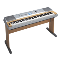
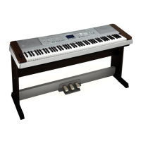
Yamaha Portable Grand YPG-535 Specifications

General IconGeneral
Number of Keys88
Keyboard TypeGraded Hammer Standard (GHS) keyboard
Voices500
Styles160
DisplayLCD
Amplifiers6W x 2
Preset Songs30
USBYes
Sustain PedalYes
Touch SensitivityYes
Featured VoicesElectric Piano, Strings
Speakers12 cm x 2
EffectsReverb, Chorus
RecordingYes
ConnectionsUSB TO HOST
HeadphonesYes
Power SupplyAC adapter
Polyphony64-note

Summary

Keyboard Specifications

Panel Layout Overview

Front Panel Controls

Identification and description of all controls on the front panel of the keyboard.

Circuit Board Layout and Wiring

Disassembly Procedures

Upper Case Internal Component Disassembly

Procedures for removing various internal boards and components from the upper case.

LSI Pin Description Details

Circuit Board Identification

Test Program Guide

Test Program Preparation and Entry

Information on preparing for and entering the diagnostic test program.

Test Program Execution and Results

Procedures for executing tests and interpreting results.

User Data Backup and Management

USB Flash Memory Operations

Instructions for connecting, formatting, saving, and loading data via USB.

Parts List Information

Assembly Parts Breakdown

Detailed parts list for overall, stand, lower case, and keyboard assemblies.

System Block Diagram

Overall Circuit Diagrams

Related product manuals