Do you have a question about the Yamaha PortaTone PSR-350 and is the answer not in the manual?
| Styles | 100 |
|---|---|
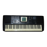
| Display | LCD |
| MIDI | Yes |
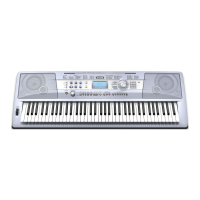
| Speakers | 12cm x 2 |
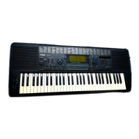
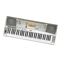
| Type | Portable Keyboard |
| Brand | Yamaha |
| Model | PSR-350 |
| Weight | 5.5 kg |
| Effects | Reverb, Chorus, DSP |
| Keyboard | 61 keys |
| Polyphony | 32 notes |
| Amplifiers | 2.5W + 2.5W |
| Power Supply | PA-3B AC adaptor or six 'D' size batteries |
| Connections | MIDI In/Out |
Notice regarding hazardous chemicals used in product manufacturing and safe handling.
Guidelines for authorized personnel to follow for safe servicing.
Warnings about static electricity and proper component handling during service.
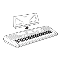
Details on keyboard features, touch response, display, and panel controls.
Information on voice polyphony, styles, effects, and song functions.
Specifications for MIDI, jacks, power, dimensions, and weight.
Diagram and identification of controls on the top panel.
Identification of input/output jacks and connectors on the rear panel.
Diagram showing component placement on the lower case side.
Diagram showing component placement on the upper case side.
Steps for removing the lower case assembly, battery cover, and spring terminal.
Procedure for removing speakers, shield boxes, and AM circuit board.
Instructions for removing PN, PW, VR, LCD circuit boards and floppy disk drive.
Steps for disassembling and reassembling the keyboard mechanism.
Detailed pin descriptions for CPU, Floppy Disk Controller, and LCD Driver ICs.
Block diagrams for logic, audio, converter, and amplifier ICs.
Diagram showing the overall circuit of DM, AM, VR, PW, TW-L/R components.
Diagram showing the overall circuit of PN, LCD, MKS5, MK-L, MK-H components.
Instructions for preparing and entering the service test mode.
Procedure for running tests and interpreting results on the LCD.
List of available test programs with their respective functions and criteria.
Details on data retained when power is off (User Songs, Settings).
Procedure to restore the unit to factory preset condition.
Exploded view and part numbers for the overall assembly.
Exploded view and part numbers for the keyboard assembly.
Comprehensive list of electrical components, part numbers, and descriptions.