Do you have a question about the Yamaha R-840 and is the answer not in the manual?
Details components marked with 'A' that require exact replacement parts.
Explains how to measure and the acceptable limit for leakage current.
Warns about chemicals in the product and safe handling practices.
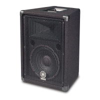
Lists technical specifications for the R-840 receiver, including audio and FM sections.
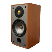
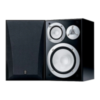
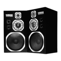
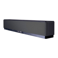
Provides technical specifications for the NS-BP300 speaker, including driver and impedance details.
Step-by-step instructions for removing the top cover of the unit.
Instructions for removing the amplifier unit, including PCB and rear panel disconnection.
Guides on how to remove the front panel unit, including screw and hook details.
Lists necessary tools and materials for firmware updates, including software and cables.
Details the physical connection setup for the firmware update process.
Step-by-step guide on how to perform the firmware update using the software.
Continues the step-by-step guide for firmware updating, covering setting baud rate and erasing.
Concludes the firmware update steps, including final checks and disconnection.
Outlines steps and precautions before and during firmware updating.
Explains how to verify the firmware version and checksum after updating.
Lists main menu items and their corresponding sub-menu functions for diagnostics.
Explains how to enter the self-diagnostic mode using button combinations.
Explains how to navigate through the diagnostic menus using knobs and keys.
Details the sub-menus for firmware version, checksum, and DAB module version.
Continues AD Data Check, detailing THM, VOLUME, BASS, TBL, and BAL detection.
Completes AD Data Check, covering KEY and DST detection.
Explains the DSP/RST function and History 1-4 checks.
Covers VER/DEST/SUM and DISPLAY CHECK menus.
Details how to start diagnostics with protection functions disabled.
Details checking A/D conversion values for PS1, PS2, and DC detection.
Includes AD DATA CHECK and PROTECTION HISTORY menus.
Outlines the procedure for confirming idling current of the amplifier unit.
Provides important notes regarding amplifier repair and temperature correction.
Provides pin assignments and internal block diagram for the main microprocessor.
Concludes microprocessor pin function details, including key and destination detection.
Shows pin connection diagrams for various integrated circuits used in the unit.
Part 1 of the schematic diagram for the FUNCTION section.
Part 2 of the schematic diagram for the FUNCTION section.
Part 3 of the schematic diagram for the FUNCTION section.
Part 1 of the schematic diagram for the MAIN section.
Part 2 of the schematic diagram for the MAIN section.
Part 3 of the schematic diagram for the MAIN section.
Part 4 of the schematic diagram for the MAIN section.
Schematic diagram for the DAB module.
Details on significant ICs like LC72725KM, NJM2752RB0, NJW1194V, etc.
| Amplifier class | - |
|---|---|
| Audio output channels | 2.1 channels |
| Peak power per channel | 130 W |
| Signal-to-Noise Ratio (SNR) | 100 dB |
| Total Harmonic Distortion (THD) | 0.04 % |
| Speakers connectivity type | Clamp terminals |
| Purpose | Home |
| Product color | Silver |
| Connectivity technology | Wired |
| Depth | 348 mm |
|---|---|
| Width | 215 mm |
| Height | 111 mm |
| Weight | 5700 g |