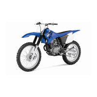
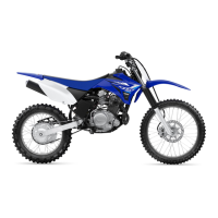
This document is an owner's service manual for the Yamaha TT-R125LW(M) motorcycle, covering operation, inspection, basic maintenance, and tuning. It is the first edition, published in January 2000 by Yamaha Motor Co., Ltd. The manual emphasizes that the TT-R125LW(M) is designed for off-road use only by young operators under adult instruction and supervision and is not suitable for on-road use. It also states that the machine is designed to carry only the operator, with no passengers.
The manual highlights several critical safety warnings:
- Gasoline is highly flammable: Always turn off the engine when refueling, avoid spilling fuel on hot parts, and never refuel while smoking or near open flames. In case of ingestion, inhalation of vapor, or eye contact, seek immediate medical attention. If spilled on skin or clothing, wash immediately and change clothes.
- Leaving the machine unattended: Always turn off the engine. When parking, be aware that the engine and exhaust pipe/muffler may be hot, and park where pedestrians or children are unlikely to touch it. Avoid parking on slopes or soft ground to prevent overturning.
- Transportation: When transporting the machine in another vehicle, ensure it is kept upright and the fuel cock is turned to "OFF" to prevent fuel leakage.
- Engine operation in enclosed areas: Never start or run the engine in a closed area due to poisonous exhaust fumes. Always operate in a well-ventilated area.
- Protective gear: Always wear a helmet, gloves, boots, trousers, and jacket for motocross riding.
- Riding practices: Do not ride on public streets or roads. Do not run the engine inside a building. This is a one-seater motorbike; do not carry passengers. Learn to ride properly and consult parents for any questions. Do not touch hot or moving parts. Shift the transmission into neutral before starting the engine.
The manual provides a description of the motorcycle's components and their functions.
- Machine Identification: The vehicle identification number is stamped on the right side of the steering head pipe. The engine serial number is stamped on the elevated part of the right side of the engine. A model label is affixed to the frame under the rider's seat. These numbers are crucial for ordering parts and identification in case of theft.
Control Functions:
- Engine Stop Switch: Located on the left handlebar, it stops the engine when pushed.
- Clutch Lever: Located on the left handlebar, it engages or disengages the clutch. Pull rapidly and release slowly for smooth starts.
- Shift Pedal: Located on the left side of the engine, it shifts the 5-speed constant-mesh transmission.
- Kickstarter Crank: Rotate away from the engine, push down lightly until gears engage, then kick smoothly and forcefully to start. Ensure the transmission is in neutral before starting.
- Throttle Grip: Located on the right handlebar, it accelerates (turn toward you) or decelerates (turn away from you) the engine.
- Front Brake Lever: Located on the right handlebar, it activates the front brake when pulled.
- Rear Brake Pedal: Located on the right side of the machine, it activates the rear brake when pressed down.
- Fuel Cock: Supplies fuel from the tank to the carburetor and filters it. It has three positions: "OFF" (no fuel flow, use when engine is off), "ON" (fuel flows to carburetor, for normal riding), and "RES" (reserve, use when main fuel runs out, refuel immediately and return to "ON").
- Starter Knob (Choke): Used for cold starts by supplying a richer air-fuel mixture. Pull out to open the circuit for starting, push in to close when the engine warms up.
- Fuel Tank Cap: Remove by turning counterclockwise. Do not overfill the fuel tank or spill fuel on the hot engine.
- Sidestand: Used to support the machine when standing or transporting. Never apply additional force to it, and always hold it up before starting out.
Fuel:
- Recommended Fuel: Regular gasoline (unleaded for USA, CDN, EUROPE, AUS, NZ). Always use fresh, name-brand gasoline.
- Fuel Tank Capacity: Total: 6.6 L (1.45 Imp gal, 1.74 US gal). Reserve: 1.9 L (0.42 Imp gal, 0.5 US gal).
- Fuel Level: Do not fill above the bottom of the filler tube to prevent overflow due to heat expansion.
Starting and Break-in:
- Pre-operation Check: Perform all checks in the pre-operation checklist before starting.
- Cold Engine Start: Shift to neutral, turn fuel cock to "ON," fully open starter knob (choke). With throttle closed, kickstart forcefully. Idle or run slightly higher for 1-2 minutes until warm. Turn off starter knob when engine responds normally to throttle. Do not warm up for extended periods.
- Warm Engine Start: Do not use starter knob. Open throttle slightly, kickstart forcefully.
- Break-in: Crucial for fitting moving parts and accustoming the rider. Avoid full-throttle for the first 5 hours. After trial run, check for loose parts, oil leakage, slack cables, drive chain, and loose spokes.
- Post-Replacement Break-in: If engine-related parts (cylinder, piston, rings, valve, camshaft, crankshaft, clutch, transmission gear, shift fork) are replaced, break in as a new machine.
Torque-Check Points:
The manual lists various components and their tightening points, including engine mounting, muffler, steering, suspension, wheels, brakes, and fuel system. It refers to the "MAINTENANCE SPECIFICATIONS" section in Chapter 2 for specific torque values.
Cleaning and Storage:
- Cleaning: Frequent cleaning enhances appearance, performance, and component life. Before washing, block the exhaust pipe to prevent water entry. Apply degreaser to greasy engine parts (avoid chain, sprockets, wheel axles). Rinse with a garden hose (low pressure to avoid water seepage into bearings, forks, brakes, seals). Wash with warm water and mild detergent. Rinse immediately, dry with a soft towel. Dry and lubricate the drive chain. Clean the seat with vinyl upholstery cleaner. Apply automotive wax to painted/chromed surfaces (avoid cleaner-waxes with abrasives). After cleaning, idle the engine for several minutes.
- Storage (60 days or more): Drain fuel tank, lines, and carburetor float bowl. Remove spark plug, pour 1 tablespoon of SAE 10W-30 motor oil into the hole, reinstall plug, and kick engine over several times to coat cylinder walls. Remove, clean, and lubricate the drive chain, then reinstall or store in a plastic bag. Lubricate all control cables. Block the frame to raise wheels off the ground. Tie a plastic bag over the exhaust pipe outlet. In humid/salt-air environments, coat exposed metal surfaces with light oil (avoid rubber parts, seat cover). Make necessary repairs before storage.
Specifications (Chapter 2):
-
General Specifications:
- Model Name: TT-R125LWM (USA-except California, CDN, AUS, NZ), TT-R125LWMC (USA for California), TT-R125LW (EUROPE).
- Model Code Number: 5HP4 (USA, AUS, NZ, EUROPE), 5HP5 (CDN).
- Dimensions: Overall length 1,885 mm (74.2 in) for USA, AUS, NZ, EUROPE; 1,890 mm (74.4 in) for CDN. Overall width 795 mm (31.3 in). Overall height 1,085 mm (42.7 in). Seat height 805 mm (31.7 in). Wheelbase 1,270 mm (50.0 in). Minimum ground clearance 295 mm (11.6 in).
- Basic Weight (with oil and full fuel tank): 84 kg (185 lb).
- Engine Type: Air-cooled 4-stroke, SOHC, single cylinder, forward inclined.
- Displacement: 123.7 cm³ (7.55 cu.in).
- Bore × Stroke: 54.0 × 54.0 mm (2.126 × 2.126 in).
- Compression Ratio: 10.0:1.
- Starting System: Kickstarter.
- Lubrication System: Wet sump.
- Engine Oil: Yamalube 4 (10W-30) or SAE 10W-30 type SE motor oil for temperatures at -10°C (10°F) or higher. Yamalube 4 (20W-40) or SAE 20W-40 type SE motor oil for temperatures at 5°C (40°F) or higher. API "SE" or higher grade (except for USA and CDN).
- Oil Capacity: Periodic oil change: 1.0 L (0.88 Imp qt, 1.06 US qt). Total amount: 1.2 L (1.06 Imp qt, 1.27 US qt).
- Air Filter: Wet type element.
- Carburetor: Type VM20SS, Manufacturer MIKUNI.
- Spark Plug: Type CR7HSA/U22FSR-U, Manufacturer NGK/DENSO, Gap 0.6 ~ 0.7 mm (0.02 ~ 0.03 in).
- Clutch Type: Wet, multiple-disc.
- Transmission: Primary reduction system: Gear, ratio 68/19 (3.578). Secondary reduction system: Chain drive, ratio 54/13 (4.154). Type: Constant mesh, 5-speed. Operation: Left foot operation. Gear ratios provided for all 5 gears.
- Chassis: Frame type: Diamond. Caster angle: 28.5°. Trail: 107 mm (4.21 in).
- Tires: Type: With tube. Size (front): 70/100-19 42M. Size (rear): 90/100-16 52M. Manufacturer: INOUE RUBBER. Pressure (front and rear): 100 kPa (1.00 kg/cm², 15 psi).
- Brake: Front brake type: Single disc brake, operation: Right hand. Rear brake type: Drum brake, operation: Right foot.
- Suspension: Front: Telescopic fork. Rear: Swingarm (link type monocross suspension).
- Shock Absorber: Front: Coil spring/oil damper. Rear: Coil spring/gas, oil damper.
- Wheel Travel: Front: 180 mm (7.09 in). Rear: 168 mm (6.61 in).
- Electrical: Ignition system: CDI magneto.
-
Maintenance Specifications: Detailed limits and standards for engine components (cylinder head warp, cylinder bore, camshaft runout, valve clearance, valve dimensions, valve spring free length, compressed pressure, tilt limit, piston clearance, piston pin diameter, piston ring end gap and side clearance, crankshaft width, runout, big end side clearance, clutch friction plate thickness, clutch plate thickness and warp, clutch spring free length, push rod bending limit, shifter type, kick starter friction force, carburetor settings, oil pump clearances).
-
Chassis Maintenance Specifications: Steering bearing type, front suspension travel, fork spring free length, spring rate, oil capacity and level, inner tube diameter, rear suspension travel, spring free length, fitting length, spring rate, gas pressure, wheel type, rim size, rim runout, drive chain type, number of links, chain slack, chain length, front disc brake outside diameter and thickness, deflection limit, pad thickness, master cylinder inside diameter, caliper cylinder inside diameter, brake fluid type, rear drum brake type, drum inside diameter, lining thickness, shoe spring free length, brake lever free play, brake pedal position and free play, clutch lever free play, throttle grip free play.
-
Electrical Maintenance Specifications: CDI magneto model/manufacturer, charging coil resistance, pickup coil resistance, CDI unit model/manufacturer, ignition coil model/manufacturer, minimum spark gap, primary and secondary coil resistance.
-
General Torque Specifications: A chart for standard fasteners (Nm, m·kg, ft·lb) based on thread size.
-
Definition of Units: Explanations for units used in the manual (mm, cm, kg, N, Nm, m·kg, Pa, N/mm, L, cm³, r/min).
-
Cable Routing Diagram: Visual guides for proper routing of various cables and hoses to ensure correct function and prevent interference.
Regular Inspection and Adjustments (Chapter 3):
- Maintenance Intervals: A schedule for checks and maintenance jobs at initial (10 hours/1 month) and regular (60 hours/6 months, 120 hours/12 months) intervals. Some items require special tools and technical skills and should be serviced by a Yamaha dealer.
- Pre-operation Inspection: A checklist of items to verify before each ride or break-in, including fuel, engine oil, gear shifter, clutch, throttle grip, brakes, drive chain, wheels, steering, front forks, rear shock absorber, cables, muffler, sprocket, lubrication, bolts, nuts, and lead connectors.
- Engine:
- Clutch Adjustment: Check and adjust clutch lever free play (10-15 mm).
- Throttle Cable Adjustment: Check and adjust throttle grip free play (3-5 mm).
- Air Filter Cleaning: Remove and clean the element with solvent. Do not twist the element. Replace if damaged. Never run the engine without the air filter element.
- Engine Oil Level Inspection: Warm up engine, place machine upright, check dipstick level (between max/min marks). Add oil if low. Do not add chemical additives or use oils labeled "ENERGY CONSERVING II" or higher.
- Engine Oil Replacement: Drain oil, replace copper washer, refill with recommended oil.
- Oil Pressure Inspection: Loosen check bolt, run engine until oil seeps out. If no oil after 1 minute, turn off engine and inspect. Tighten check bolt (7 Nm).
- Pilot Air Screw Adjustment: Adjust pilot air screw (factory-set, typically 2-1/2 to 3-1/2 turns out).
- Engine Idling Speed Adjustment: Warm up engine, attach inductive tachometer, adjust idling speed (1,300-1,500 r/min).
- Valve Clearance Inspection and Adjustment: Check valve clearance (intake: 0.08-0.12 mm, exhaust: 0.10-0.14 mm) when engine is cool and piston is at TDC on compression stroke. Adjust by loosening locknut and turning adjuster. Tighten locknut (8 Nm).
- Spark Arrester Cleaning (For USA): Ensure exhaust is cool. Remove bolt, pull out arrester, clean carbon deposits with a wire brush. Reinstall and tighten bolt (10 Nm).
- Chassis:
- Brake System Air Bleeding: Bleed if system disassembled, hose loosened/removed, fluid low, or operation faulty. Use DOT #4 fluid.
- Front Brake Adjustment: Check and adjust brake lever free play (2-5 mm). Ensure no brake drag.
- Rear Brake Adjustment: Check and adjust brake pedal free play (20-30 mm). Ensure no brake drag.
- Brake Pedal Height Adjustment: Check and adjust pedal height (1 mm below footrest top).
- Front Brake Pad Inspection and Replacement: Inspect pad thickness (limit 0.8 mm). Replace as a set if worn.
- Rear Brake Shoe Inspection: Inspect lining wear (limit 2.0 mm). Replace shoes and springs as a set if worn.
- Brake Fluid Level Inspection: Check fluid level (to "LOWER" line). Use DOT #4. Do not mix fluids or allow contaminants.
- Sprockets Inspection: Inspect sprocket teeth for excessive wear. Replace drive, driven sprockets, and drive chain as a set.
- Drive Chain Inspection and Adjustment: Remove, clean, and lubricate drive chain. Measure length (limit 121.4 mm for 10 links). Check stiffness. Adjust slack (35-60 mm) by loosening axle nut and turning pullers. Tighten axle nut (60 Nm).
- Front Fork Inspection: Check for smooth action and oil leakage. Repair or replace if necessary.
- Rear Shock Absorber Assembly Inspection: Check for smooth swingarm action, abnormal noise, oil/gas leakage. Repair or replace if necessary.
- Rear Shock Absorber Spring Preload Adjustment: Adjust preload by turning the adjuster.
- Tire Pressure Check: Measure pressure when cold (100 kPa). Check for loose bead stoppers or tilted valve stems, correct tire position if necessary.
- Spokes Inspection and Tightening: Inspect for bends/damage (replace) or looseness (retighten). Tighten front spokes (2 Nm), rear spokes (3 Nm).
- Wheel Inspection: Check for runout (limit 2.0 mm radial/lateral) and bearing free play (replace if present).
- Wheel Axle Inspection: Measure bends (limit 0.5 mm). Do not straighten a bent axle.
- Steering Head Inspection and Adjustment: Elevate front wheel, check steering shaft for free play (adjust if present) and smooth action. Adjust steering ring nut (initial tightening 38 Nm, final tightening 20 Nm).
- Swingarm Inspection: Inspect bushings for damage/pitting (replace as a set), dust covers for damage (replace), and swingarm for damage/bends/cracks (replace).
- Relay Arm Inspection: Inspect collars, bushings, oil seals, dust covers, and relay arm for damage/pitting/bends/cracks (replace as a set if necessary).
Engine (Chapter 4):
Detailed procedures for removal, disassembly, inspection, assembly, and installation of engine components:
- Seat, Fuel Tank, and Side Covers
- Muffler
- Carburetor (including throttle valve, jet needle, float level, float, coasting enricher)
- Cylinder Head (including tappet covers, spark plug, timing chain, camshaft sprocket, cylinder head warpage)
- Camshaft and Rocker Arms (including rocker arm shafts, camshaft lobes, rocker arm inside/outside diameter)
- Valves and Valve Springs (including valve sealing, cotters, retainers, springs, stem seals, seats, stem-to-guide clearance, margin thickness, runout, valve face, valve seats)
- Cylinder and Piston (including piston pin clips, piston pin, piston rings, cylinder/piston walls, piston-to-cylinder clearance, piston pin-to-piston clearance, piston ring side clearance and end gap, piston/cylinder combination)
- Clutch and Primary Driven Gear (including clutch boss, primary drive gear, push lever, clutch spring, friction plate, clutch plate, push rod)
- Oil Pump (including rotary filter, oil pump drive/driven gear, housing, cover, tip/side/housing-rotor clearances, oil strainer)
- Kick Axle and Shift Shaft (including kick axle assembly, segment, kick idle gear, kick axle clip, shift shaft, stopper lever)
- CDI Magneto (including rotor, woodruff key, stator, pickup coil)
- Engine Removal
- Crankcase, Crankshaft, and Balancer (including crankcase bolts, lead guide, clutch cable holder, crankcase separation, bearings, crankshaft runout, connecting rod big end side clearance, crank width, timing chain, timing chain guide, balancer)
- Transmission, Shift Cam, and Shift Fork (including main axle, drive axle, gears, shift fork, shift cam, shift fork guide bar, push rod)
Chassis (Chapter 5):
Detailed procedures for removal, disassembly, inspection, assembly, and installation of chassis components:
- Front Wheel (including axle nut, washer, wheel axle, front wheel, collar, oil seal, wheel bearing, spacer, brake disk, wheel runout, wheel axle bends, brake disc deflection and thickness)
- Front Brake (including brake master cylinder cap, diaphragm, bleed screw, brake caliper, brake caliper piston, piston seal kit, brake master cylinder inner surface, diaphragm, piston, cylinder cup, brake caliper bracket, guide pin, sleeve boot, pin boot, brake caliper support bolt, brake hose, copper washer, union bolt)
- Rear Wheel and Rear Brake (including brake rod, axle nut, drive chain puller, wheel axle, drive chain, rear wheel, collar, brake shoe plate assembly, wheel bearing, spacer, brake shoe, spring, brake camshaft lever, wear indicator plate, brake camshaft, wheel runout, wheel axle bends, brake drum inner surface, brake shoe lining thickness, brake drum inside diameter, wheel sprocket, lock washers)
- Front Fork (including cap bolt, dust seal, stopper ring, damper rod, inner tube, oil flow stopper, piston metal, outer tube, fork spring, oil level)
- Handlebar (including clutch cable, clutch lever, engine stop switch, brake master cylinder, grip caps, throttle cable, throttle grip assembly, handlebar bends/cracks)
- Steering (including steering stem nut, upper bracket, special washer, upper ring nut, rubber washer, lower ring nut, lower bracket, bearing cover, bearing inner/outer race, lower bearing, steering stem bends/damage)
- Swingarm (including drive chain guard, drive chain support, drive chain guide, dust cover, collar, connecting arm, oil seal, bushing, relay arm, pivot shaft, swingarm side play, swingarm up/down movement)
- Rear Shock Absorber Assembly (including bolt, bushing, damper rod, shock absorber, spring)
Electrical (Chapter 6):
- Electrical Components and Wiring Diagram: Lists electrical components (CDI unit, engine stop switch, ignition coil, CDI magneto, spark plug) and their color codes. Provides a wiring diagram.
- Ignition System:
- Inspection Steps: Flowchart for checking ignition system components (spark plug, connections, engine stop switch, ignition coil, CDI magneto, CDI unit).
- Spark Gap Test: Disconnect spark plug cap, connect dynamic spark tester, kickstart, check spark gap (minimum 6.0 mm). Start engine and increase gap until misfire occurs (for USA and CDN only).
- Couplers and Leads Connection Inspection: Check for rust, dust, looseness, or short circuits.
- Engine Stop Switch Inspection: Check continuity when pushed (not continuous) and freed (continuous).
- Ignition Coil Inspection: Measure primary coil resistance (0.18-0.28 Ω) and secondary coil resistance (6.3-9.5 kΩ).
- CDI Magneto Inspection: Measure pickup coil resistance (248-372 Ω) and charging coil resistance (688-1,032 Ω).
- CDI Unit Inspection: Check all electrical components; if no fault is found, replace the CDI unit and recheck.
The manual includes numerous illustrations, special tools, and torque specifications to guide the user through maintenance and repair procedures. It emphasizes the importance of using genuine Yamaha parts and recommended lubricants.