EasyManua.ls Logo

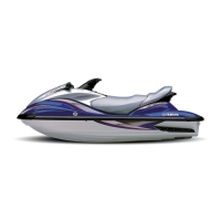
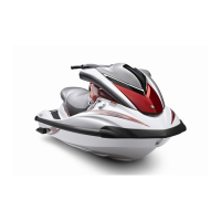
Yamaha WaveRunner FX140 Service Manual

Yamaha WaveRunner FX140
868 pages
To Next Page IconTo Next Page
Page #1 background imageLoading...
Page #1 background image
460079
WaveRunner
FX140
F1B-28197-ZE-C1
SERVICE MANUAL
MANUEL D’ENTRETIEN
WARTUNGSHANDBUCH
MANUAL DE SERVICIO
E
F
D
ES
D

Table of Contents

Other manuals for Yamaha WaveRunner FX140

Questions and Answers:

Yamaha WaveRunner FX140 Specifications

General IconGeneral
ManufacturerYamaha
ModelWaveRunner FX140
Fuel Capacity18.5 gallons
Length132.7 inches
Horsepower140 hp
Starter SystemElectric
Lubrication SystemWet Sump
CategoryPersonal Watercraft (PWC)
Engine Type4-Cylinder, 4-Stroke
Displacement1052cc
Fuel TypeGasoline
Seating Capacity3
Fuel DeliveryElectronic Fuel Injection (EFI)
Cooling SystemWater-cooled
Passenger Capacity3

Summary

CHAPTER 1 GENERAL INFORMATION

IDENTIFICATION NUMBERS

Details regarding primary ID, engine serial, jet pump, and hull identification numbers.

SAFETY WHILE WORKING

Information on fire prevention, ventilation, self-protection, and handling of hazardous materials.

CHAPTER 2 SPECIFICATIONS

TIGHTENING TORQUES

Lists specified torques for fasteners, crucial for correct assembly and preventing damage.

CHAPTER 4 FUEL SYSTEM

FUEL TANK AND FUEL PUMP MODULE

Details exploded view, removal/installation chart, and service points for fuel tank and pump.

FUEL INJECTION SYSTEM

Covers exploded diagrams, removal/installation charts, and service points for fuel injection components.

CHAPTER 5 POWER UNIT

ENGINE UNIT

Provides exploded diagrams, removal/installation charts, and service points for the engine unit.

CHAPTER 6 JET PUMP UNIT

JET PUMP UNIT

Provides exploded diagrams and removal/installation charts for the jet pump unit.

CHAPTER 7 ELECTRICAL SYSTEM

ELECTRICAL BOX AND IGNITION COIL BOX

Details exploded diagram, removal/installation chart, and service points for the electrical box and ignition coil box.

IGNITION SYSTEM

Covers wiring diagrams, spark plug gap, ignition system peak voltage, battery, fuses, spark plugs, and ignition coil.

CHAPTER 8 HULL AND HOOD

CHAPTER 9 TROUBLE ANALYSIS

OPERATING

Explains how to connect the computer, open the diagnostic system, select commands, and perform tests.

TROUBLESHOOTING

Offers a chart to diagnose common problems and their corresponding solutions or reference chapters.

Related product manuals