SPEC
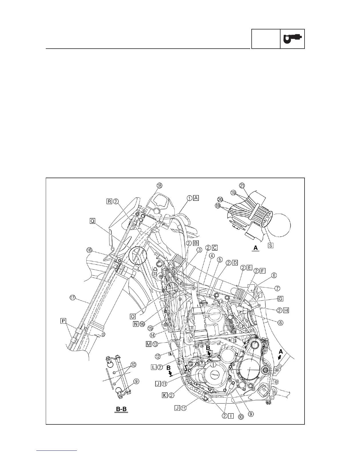
CABLE ROUTING DIAGRAM
9
CABLE ROUTING DIAGRAM
1 Fuel tank breather hose
2 Clamp
3 Diode
4 Wire harness
5 Hot starter cable
6 Negative battery lead
7 Starter motor lead
8 TPS (throttle position sensor) lead
9 Neutral switch lead
0 Oil hose
q Hose holder
w Radiator hose 4
e Cylinder head breather hose
r AC magneto lead
t Radiator hose 1
y Oil tank breather hose
u Brake hose
i Hose guide
o Carburetor breather hose
t Overflow hose
a Coolant reservoir tank breather
å Insert the fuel tank breather
hose into the hole in the steer-
ing shaft cap.
∫ Fasten the diode of the wire
harness and rectifier/regulator
lead (at its protecting tube) to
the frame at the white tape for
the diode with a plastic locking
tie and cut off the tie end.
ç Fasten the wire harness, rectifi-
er/regulator lead, coolant reser-
voir hose and hot starter cable
to the frame with a plastic lock-
ing tie and cut off the tie end.
∂ Fasten the wire harness, rectifi-
er/regulator lead and coolant
reservoir hose to the frame with
a plastic locking tie and cut off
the tie end.
´ Fasten the wire harness to the
frame at its white tape with a
plastic locking tie and cut off the
tie end.

 Loading...