PERIODIC MAINTENANCE AND MINOR REPAIR
6-28
6
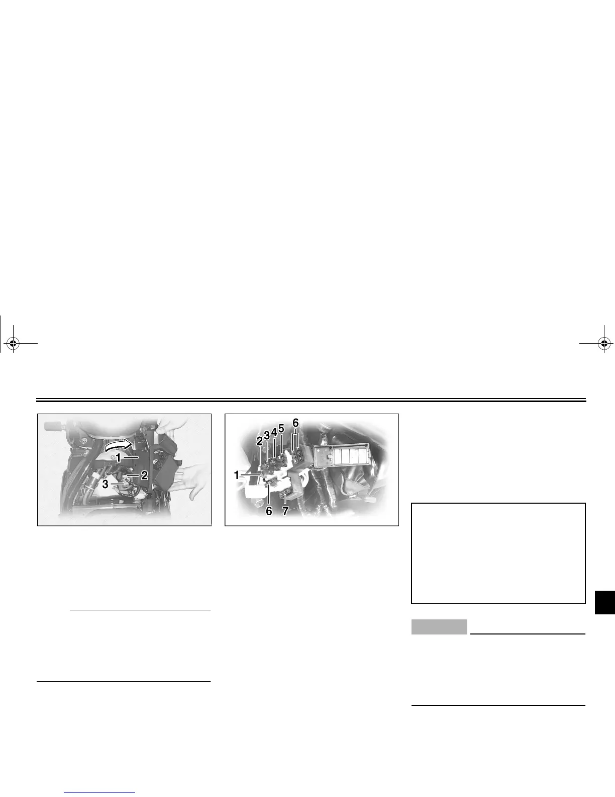
3. Pull the ignitor unit panel outward
to the right.
NOTE:
@
To install a quick fastener, push its pin
back so that it will protrude from the
fastener head, then insert the fastener
and push the protruding pin in until it is
flush with the fastener head.
@
The fuse box, which contains the fuses
for the individual circuits, is located in-
side the storage compartment. (See
page 3-14 for storage compartment
cover removal and installation proce-
dures.)
If a fuse is blown, replace it as follows.
1. Turn the key to “OFF” and turn off
the electrical circuit in question.
2. Remove the blown fuse, and then
install a new fuse of the specified
amperage.
EC000103
@
Do not use a fuse of a higher amper-
age rating than recommended to
avoid causing extensive damage to
the electrical system and possibly a
fire.
@
3. Turn the key to “ON” and turn on
the electrical circuit in question to
check if the device operates.
1. Ignitor unit panel
2. Spare fuse
3. Main fuse
1. Fuse box
2. Odometer fuse
3. Ignition fuse
4. Headlight fuse
5. Carburetor heater fuse
6. Spare fuse (× 3)
7. Signaling system fuse
Specified fuses:
Main fuse: 30 A
Odometer fuse: 5 A
Ignition fuse: 10 A
Headlight fuse: 15 A
Carburetor heater fuse: 15 A
Signaling system fuse: 10 A
E_5KS.book Page 28 Monday, August 21, 2000 10:48 AM
 Loading...