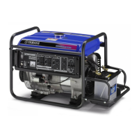
Do you have a question about the Yamaha YG6600D and is the answer not in the manual?
Record identification numbers for spare parts and theft prevention.
Machine serial number is stamped in a specific location.
Details warranty duration for private and commercial use.
Lists failures not covered by warranty.
Outlines owner's duties for warranty.
Specifies warranty period for EC- and YG-series.
Lists failures not covered by warranty.
Outlines owner's duties for warranty.
Provides contact information for customer support and warranty issues.
Instructs owners on how to update their address for recalls.
Alerts users to electrocution risk and isolation switch needs.
Warns about hot exhaust components.
Provides engine details like emission compliance and fuel type.
Alerts users to electrocution risk and isolation switch needs.
Warns about hot exhaust components.
Provides engine details like emission compliance and fuel type.
Warns about toxic exhaust fumes and ventilation needs.
Advises on safe fuel handling, refueling, and spill response.
Warns about hot engine and muffler components.
Provides guidelines to prevent electric shock.
Advises against connecting to commercial power or in parallel.
Details mandatory isolation switch installation for building connections.
Specifies requirements for safe and durable extension cords.
Identifies various components of the EF/EDL series generators.
Identifies various components of the YG series generators.
Identifies control elements for EF/EDL series generators.
Identifies control elements for YG series generators.
Explains the oil warning system's function and effect on the engine.
Describes the function and positions of the engine switch.
Details the operation of the starter switch for YG6600DE.
Explains the automatic shutdown function of the AC switch.
Details the benefits of the economy idle switch for fuel and noise.
Explains how to adjust output voltage to the rated level.
Describes the Ground Fault Circuit Interrupter receptacle and its function.
Emphasizes checking the machine before use.
Details recommended fuel and tank capacity for all models.
Instructs on checking and filling engine oil to the correct level.
Lists recommended oil types and quantities for different models.
Stresses the importance of grounding the generator.
Details the process of installing the battery safely.
Lists pre-start actions like turning off devices and switches.
Guides on setting fuel cock and engine switch for starting.
Instructions for starting electric start models.
Instructions for starting manual start models.
Shows power output (W) for various loads and models.
Details safe AC connection procedures and cautions.
Guides on verifying rated voltage using the meter or pilot light.
Explains AC switch operation for different YG and EF models.
Outlines the steps to safely turn off the generator.
Provides a schedule for regular maintenance tasks.
Lists maintenance items and their service intervals.
Details how to check, gap, and torque the spark plug.
Guides on draining old oil and refilling with new oil.
Explains how to clean and oil the air filter element.
Details cleaning and checking the fuel cock.
Describes how to clean the fuel tank filter.
Instructions for cleaning muffler screen and spark arrester.
Instructions for cleaning muffler components for specific models.
Details removing and cleaning spark arrester and screen.
Guides on checking and refilling battery fluid with distilled water.
Details how to replace a blown fuse with the correct amperage.
Explains how to test the G.F.C.I. receptacle's functionality.
Lists common causes and solutions for engine starting issues.
Provides a step-by-step guide for diagnosing starting problems.
Guides on checking engine oil level as a troubleshooting step.
Details checking the spark plug for issues.
Troubleshooting steps specific to YG series starting issues.
Instructions for draining fuel before long-term storage.
Steps to prepare the engine for storage to prevent damage.
Guidance on storing the battery properly to maintain its charge.
Lists components related to exhaust emission control with acronyms.
Provides physical dimensions for all generator models.
Lists engine type, displacement, bore, stroke, and output.
Details AC output, voltage, frequency, current, and safety device.
Illustrates the electrical connections for the EF4000DE model.
Illustrates the electrical connections for the EF5200DE model.
Illustrates the electrical connections for the EF6600DE model.
Illustrates the electrical connections for the YG4000D model.
Illustrates the electrical connections for the YG5200D model.
Illustrates the electrical connections for the YG6600D model.
Illustrates the electrical connections for the YG6600DE model.
Details the installation of the battery tray for specific models.
Details the installation of engine hangers for specific models.
Details the installation of the optional two-wheel kit.
| Model | YG6600D |
|---|---|
| Displacement | 357 cc |
| Fuel Tank Capacity | 25 L |
| Starting System | Recoil start |
| DC Output | 12V 8.3A |


