2-1
2. Wiring
2 - 1 RS-232C Connection
The DIGITRONIK instrument with the RS-232C communication function is wired for communication as shown
below.
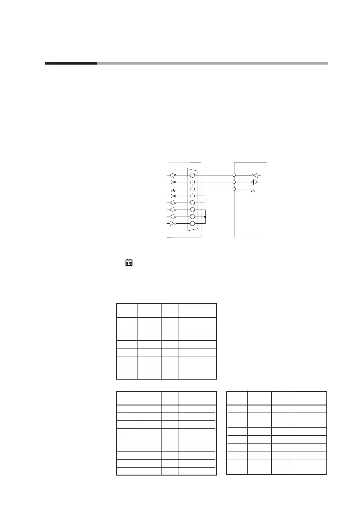
● Connection with the master station in the form of 1 to 1.
This instrument is provided with three communication terminals (RD, SD, and SG).
Data may not be output unless the other kind terminals of the master station side RS-
232C interface are short-circuited as shown in the figure below.
Usually, the pin array of the RS-232C connector of a personal computer, or the like is as
shown below (Terminal mode). In a rare case, pins (2) and (3), (4) and (5), and (6) and
(20) may be replaced with each other, respectively (MODEM mode).
Check the RS-232C pin array by referring to the instruction manual for the host
computer.
Example of connection using Yamatake Corporation CBL232FNZ02
Note
Cable catalog No. : CBL232FNZ02
(2m cable for RS-232C, 9-pin, D-Sub socket, contact - crimp style terminal)
● RS-232C connector signals
(9 pins) Example: IBM and compatibles
(25 pins) Example: PC-9800 Series (14 pins) Example: PC-9821Ne
 Loading...