EasyManua.ls Logo

Yamatake HGC303 User Manual

Yamatake HGC303
130 pages
To Next Page IconTo Next Page
Page #1 background imageLoading...
Page #1 background image
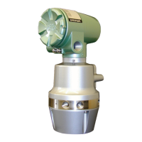
Heat Value Gas Chromatograph
Model: HGC303
Users Manual
CM2-HGC100-2001
First issue: Apr. 2001, Rev.12: Oct. 2004
HGC000001000P

Table of Contents

Questions and Answers:

Yamatake HGC303 Specifications

General IconGeneral
BrandYamatake
ModelHGC303
CategoryLaboratory Equipment
LanguageEnglish

Summary

Safety

Safety Symbols and Warnings

Explains the meaning of warning and caution symbols used in the manual.

Hazardous Areas Certifications

Details certifications for hazardous locations (ATEX, FM, TestSafe).

Installation Requirements for Hazardous Areas

Covers installation procedures and requirements for ATEX flameproof apparatus.

Installation for FM Explosionproof Apparatus

Outlines installation guidelines for FM explosionproof and flameproof apparatus.

Wiring Methods for Hazardous Locations

Specifies wiring methods for various hazardous location classes (Division 1/2, Class I/II/III).

Chapter 1: Introduction

Definition of Terms and System Components

Defines key terms like HGC303, HGM, HFA100, and lists system components.

General Information and System Overview

Provides a general description of the HGC303 and required system components.

Measuring System and Structure

Illustrates the HGC303 measuring system diagram and its main parts.

Fieldbus Communication System

Explains the FOUNDATION™ fieldbus technology used for data transfer.

Chapter 2: Installation

Unpacking and Storing Procedures

Instructions for unpacking the instrument and proper storage guidelines.

Interface Selection and Installation

Guides on selecting and installing HFA100 or NI Fieldbus-PC Interface.

HGM Software Installation

Step-by-step instructions for installing the HGM software.

Fieldbus Installation and Wiring

Details Fieldbus cable requirements, terminators, and wiring practices.

Model HGC303 Installation Details

Covers installation site selection, dimensions, examples, and piping.

Model HGC303 Wiring

Provides terminal connections and wiring diagrams for the HGC303.

Chapter 3: Operation

Starting Up and Leak Checking the HGC303

Procedures for initial startup, setting pressures, and performing leak tests.

HGM Operation and Setup

Introduces HGM functions and guides on initial setup and configuration.

Data Saving and Editing

Explains how to save, load, and edit measurement data files.

Monitoring Displays and Trend Graphs

Describes user mode displays, trend graphs, and chromatograms.

Report Generation

Details creating and viewing reports.

Configuration Mode Settings

Details various configuration options for HGC303 and HGM.

Calibration Requirements and Methods

Covers calibration requirements, manual, and auto calibration methods.

Calibration Functions and Data Management

Covers calibration functions, data tables, and reports.

GPA Mode Setup and Configuration

Guides for operating the system in GPA mode, including setup and configuration.

GPA Mode Data Handling and Monitoring

Covers saving, editing, and monitoring data specific to GPA mode.

GPA Mode Reports

Details generating and viewing reports in GPA mode.

Chapter 4: Maintenance

Carrier Gas and Filter Maintenance

Procedures for checking and changing carrier gas and filters.

Overhaul Procedures

Guidelines for the periodic overhaul of the HGC303 analyzer part.

Chapter 5: Troubleshooting

Self-Diagnostic Error Messages and Actions

Lists self-diagnostic functions, error messages, and corrective actions.

Appendix

GPA Calculation and Normalization Methods

Explains GPA calculation and different normalization methods.

Formulas for Heat Value Calculations

Provides formulas for various heat value and property calculations.

Physical Constants and Replacement Parts

Lists physical constants and diagram numbers for replacement parts.

ISO Calculation and Normalization Methods

Details ISO calculation procedures and normalization methods.

Technical Drawings

Includes detailed technical drawings and dimensions of the unit.