(1) Take out the (1 1) connecting shaft.
(2) Removethe (10) bolts8x25 (4pcs).
(3)
Remove the (6) circlip 72.
(4) Use
a
hammer and plate, to remove the (2)
ball bearing 6207 out to the left of the
(1)
dif-
ferential assembly.
(5) Separate the
(3)
ball bearing 6207 from the
(1) differential assembly and the (7) differential
bearing case with
a
hammer and plate.
(6)
Take out the (1) differential assembly..
2-18
(b) Assembly
(I) Insert the (1) differential assembly in the
(4)
final reduction gear case.
,--.
(2)
Fasten the (6) circlip 72 on the (4) final
reduction
gear
case, and then insert the (7) differ-
ential bearing case.
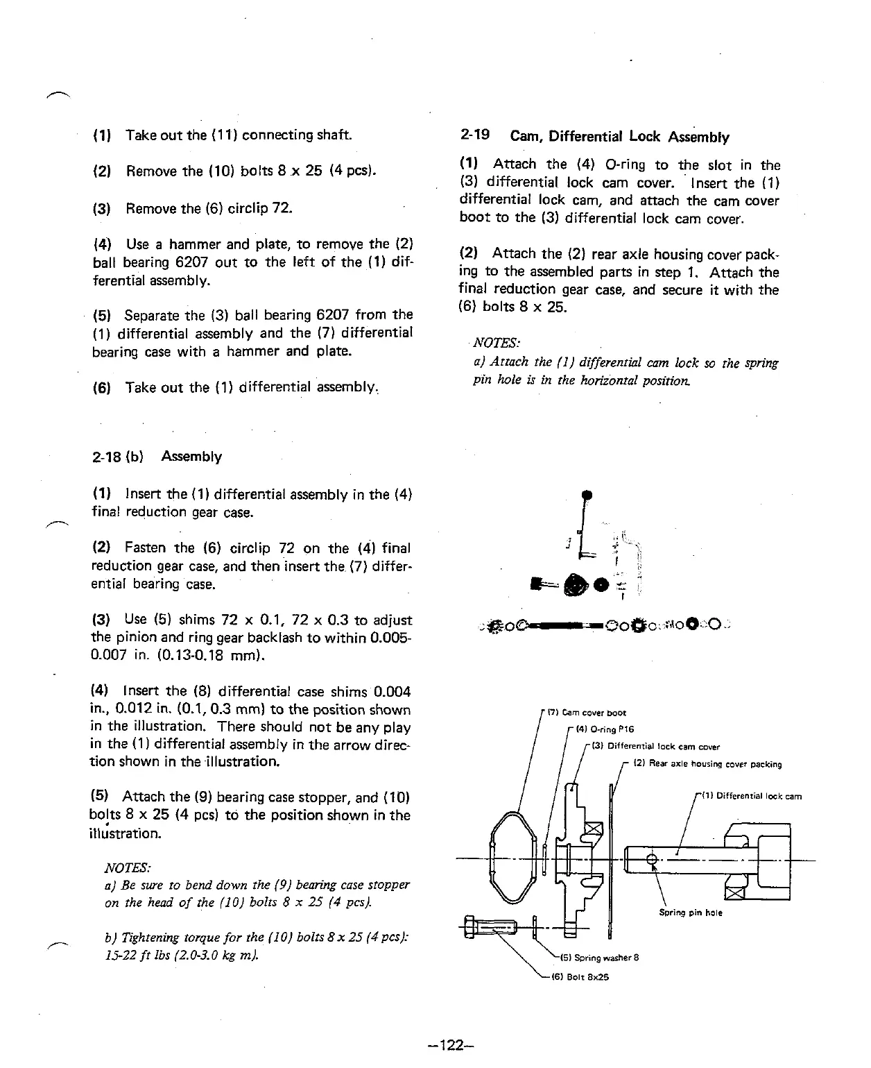
2-19 Cam, Differential
Lock
~ssembl~
(1) Attach the (4) O-ring to the slot in the
(3) differential lock cam cover. lnsert the
(1)
differential lock cam, and attach the cam cover
boot to the (3) differential lock cam cover.
(2) Attach the (2) rear axle housing cover pack-
ing to the assembled parts in step 1. Attach the
final reduction gear case, and secure
it
with the
(6) bolts 8 x 25.
NOTES:
a) Attach the
(I)
differential cam lock so the spring
pin hole is in the horizontal position
(3)
Use
(5)
shims 72 x 0.1, 72 x 0.3 to adjust
:&o@
-
~o~c::r,lo~.!o..
the pinion and ring gear backlash to within 0.005-
0.007 in. (0.13-0.i8 mm).
(4)
Insert the
(8) differential case shims 0.004
in.. 0.012 in.
(0.1,0.3 mm) to the position shown
in the illustration. There should not be any play
in the
(1 differential assembly in the arrow direc-
tion shown in theillustration.
(5) Attach the
(9)
bearing case stopper, and (10)
bolts 8 x 25
(4
pcs) to the position shown in the
illustration.
NOTES:
a) Be sure to bend down the
(9)
bearing case stopper
on the
head
of the (10) bolts
8
x
25
(4
pcs).
b)
Tightening torque for the (1 0) bolts
8
x
25
(4
pcs):
15-22
fr lbs (2.0-3.0 kg
m).
I?)
Cam
cover
boot
14) Oring
PI6
131 Differenrial
lock
cam
cwer
,-
121
Rear
axle hovrinp
cover
packing
f
Ill
Differenrial losk
cam