Do you have a question about the Yanmar EF-494T and is the answer not in the manual?
Critical safety warning about reading and understanding manual instructions before operation.
General introduction and guidance for the manual's owner.
Instructions on what to do when the machine is in abnormal condition.
Information on the duration of maintenance parts availability.
Details on how parts may be changed for improvement or upgrade.
Explanation of safety symbols, signal words, and service instructions used in the manual.
General safety precautions to follow during service and repair operations.
Information on obtaining service, troubleshooting, and spare parts availability.
Essential general precautions and guidelines to follow before and during service.
Table specifying tightening torques for various bolts and nuts according to size and material.
Identification and rating of fuses for the tractor's electrical system.
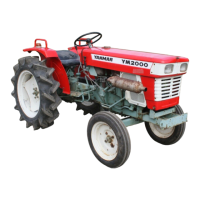
Identification of external tractor parts with corresponding numerical labels.
Diagram showing the location of various safety labels on the tractor.
Technical specifications of the tractor model, including dimensions, engine, and transmission.
Specifications for tire size, load capacity, and axle mass limits.
Table detailing inspection and replacement intervals for various tractor components.
Specifications for oils and greases recommended for the tractor's lubrication points.
Table listing fluid capacities and recommended oil types for engine, cooling, and transmission.
List of equivalent brand names and products for TF-500 transmission fluid.
Step-by-step instructions for checking and replacing engine and transmission oil.
Procedures for replacing engine oil, transmission oil line, and fuel filter elements.
Instructions for checking and replacing the tractor's cooling water.
Procedure for draining water from the fuel filter's water separator.
Steps for cleaning the air cleaner element and radiator screen for optimal performance.
Guide on how to check the battery electrolyte level and procedures for removal/installation.
Instructions for checking hoses and pipes for leaks and recommended replacement intervals.
Guidelines for inspecting electrical wiring for damage and loose connections.
Points requiring greasing and recommended intervals for daily and general maintenance.
Procedure for checking and adjusting the tractor's brake pedal play and effectiveness.
Steps for checking and adjusting the clutch pedal free play.
Guidelines for checking and adjusting the steering wheel free play.
Procedure for checking fan belt tension and adjusting or replacing it.
Method for measuring and adjusting front wheel toe-in for proper steering.
Instructions on how to check and replace blown fuses in the fuse box.
Guidance on checking tire air pressure, cracks, and damage.
Interpretation of exhaust gas colors to diagnose engine conditions.
Detailed steps for removing and installing the engine bonnet and side covers.
Procedures for removing the fuel tank cover and the fender assembly.
Steps for removing the tractor's side steps and associated covers.
Instructions for removing the seat stay, which involves draining the fuel tank.
Step-by-step guide for separating the clutch housing from the tractor.
Detailed procedures for separating the hydraulic cylinder case and the clutch housing from the transmission.
Steps for disassembling the rear axle housing, including draining oil and removing wheels.
Procedures for disassembling and reassembling the front axle unit, including the drive pinion.
Schematic illustration showing the power flow through the tractor's transmission system.
Detailed cross-section view of the transmission system, illustrating internal components and shafts.
Explanation of the main shift, reverse shift, range shift, front drive, and PTO shift modules.
Description of the constant-mesh main shift module and gear engagement.
Explanation of the constant-mesh reverse shift module and gear engagement.
Details on the constant-mesh range shift module and its gear engagement.
Explanation of the front drive engagement mechanism and power transfer.
Description of the constant-mesh PTO shift module and power output engagement.
Identification of gears within the clutch housing and reverse modules.
Step-by-step instructions for disassembling the transmission components from the clutch housing side.
Detailed view and explanation of the main shift section and its detent mechanism.
Identification of components on the right, left, and center plate sides of the transmission housing.
Procedures for disassembling the PTO module and related components.
Instructions for removing the PTO module from the transmission housing.
Overview of the rear axle's design for power transmission and its components.
Diagram illustrating the structure of the rear axle, including differential and final reduction gears.
Explanation of the differential gear mechanism, its function, and differential lock operation.
Description of the planetary final drive system, providing high torque and reduction.
Explanation of the wet-type disc brake system, including its operation and parking brake function.
Steps for disassembling and reassembling the differential system and related parts.
Procedures for removing the hydraulic cylinder case and differential lock fork.
Instructions for removing and assembling the rear axle oil seal and bearing.
Steps for removing and assembling the planetary gears and axle shaft.
Overview of the four-wheel drive front axle system and power transfer.
Diagram showing the layout of the four-wheel drive front axle components.
Detailed cross-section view of the front axle, illustrating internal mechanisms.
Explanation of front wheel alignment factors and adjustment of toe-in.
Procedure for removing the front axle bearing case, including shims.
Steps for supporting and removing the front gear box and knuckle arm.
Procedures for disassembling and reassembling the front differential section.
Steps for draining oil, removing wheels, tie rod, and front gear case.
Procedures for assembling the front axle drive pinion and bearings, including preload adjustment.
Overview of the power steering system's main components and structure.
Diagram illustrating the power steering cylinder, valve, and hydraulic pump.
Schematic of the power steering hydraulic circuit, showing oil flow and relief valve operation.
Explanation of the power steering valve's operation in neutral, during rotation, and manual rotation.
Exploded view and specifications of the front hydraulic pump.
Exploded view of the power steering cylinder assembly components.
Procedures for removing the power steering valve assembly.
Detailed steps for removing the dashboard covers and the steering valve.
Method for measuring and adjusting the power steering relief pressure.
Exploded view and parts list for disassembling the power steering valve.
Overview of the hydraulic lift unit's structure and components.
Diagram showing the hydraulic lines connecting the pump, filter, and cylinder.
Exploded view of the hydraulic cylinder case and its associated parts.
Explanation of the control valve's functions and operation.
Description of the relief valve's function and pressure setting adjustment.
Explanation of the safety valve's function and pressure setting adjustment.
Description of the stop valve's use in controlling motion and lowering speed.
Exploded view of the hydraulic pump and its parts.
Explanation of the position feedback link's role in controlling the lift arm movement.
Diagrams illustrating hydraulic oil flow in neutral, lift, and lowering operations.
Diagram showing hydraulic oil flow when the control valve is in the neutral position.
Procedures for assembling and checking the control valve.
Steps for removing and assembling the control valve from the hydraulic cylinder case.
Exploded view of the control valve components and disassembly precautions.
Procedure for measuring and adjusting the main relief pressure of the hydraulic system.
Steps for adjusting the position feedback rod to set lift arm free play.
Information on obtaining hydraulic pressure for single and double action devices.
Operation procedure for single-acting hydraulic cylinders.
Operation procedure for double-acting hydraulic cylinders.
Diagrams illustrating hydraulic pressure flow for 3-point hitch and double action PTO.
Location and operation of components related to the engine start circuit.
Identification and function of electrical components for engine starting.
Electrical schematic diagram for the engine starting system.
Tests and checks for electrical equipment, including starter motor and fuel shut off solenoid.
Measurements and checks for the fuel shut off solenoid and its coupler.
Individual component check for the fuel feed pump.
Single item check for the solenoid relay.
Information about the timer component.
Terminal connection table and single item check for the key switch.
Single item check for the combination switch functions.
Single item check for turn signal lamps.
Location and operation of components for the tractor's charging circuit.
Identification of battery, fuses, alternator, and instrument panel.
Electrical schematic diagram for the charging system.
Tests and checks for alternator, instrument panel, and key switch.
Information and checks related to the alternator.
Description of instrument panel functions and key switch operation.
Reference to key switch details in the engine start circuit section.
Location and operation of components related to the alarm circuit.
Identification of battery, fuses, sensors, and switches for the alarm system.
Electrical schematic diagram for the alarm circuit.
Tests and checks for water temperature sensor and oil pressure switch.
Information and checks for the water temperature sensor.
Single item check for the oil pressure switch.
Description of instrument panel gauges and indicators.
Reference to key switch details in the engine start circuit section.
Reference to alternator details in the charging circuit section.
Single item check for the fuel gauge sensor.
Location and operation of components for the tractor's safety circuit.
Identification of head lamps, horn, battery, fuses, relays, and switches.
Electrical schematic diagram for the safety circuit.
Tests and checks for head lamps, horn, head lamp relay, and flasher relay.
Single item check for the tractor's head lamps.
Single item check for the tractor's horn.
Single item check for the head lamp relay.
Information on the flasher relay.
Terminal connection table and single item check for the key switch.
Single item check for the combination switch.
Single item check for turn signal lamps.
Overall hydraulic circuit diagram of the tractor's systems.
Overall wiring harness diagram for the tractor's electrical system.
Diagram showing the layout and connections of the tractor's wiring harness.
Diagram showing the physical locations of various electrical components on the tractor.
Detailed wiring diagram illustrating the electrical connections and circuits.