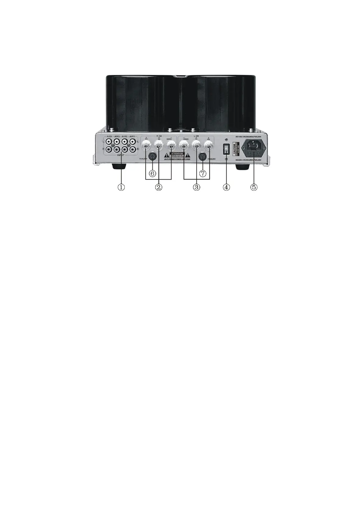
Back Plan Function Diagram
① Signal Input Plughole:AUX1, AUX2, AUX3, AUX4
② Right Channel (R.CH) output terminals (+, -) ,they should be connected with the positive pole
and negative pole of the speaker terminals respectively; and the output impedances are 4Ω-8Ω.
③ Left Channel (L.CH) output terminals (+, -) ,they should be connected with the positive pole and
negative pole of the speaker terminals respectively; and the output impedances are 4Ω-8Ω.
④ Voltage Selection Key
ATTENTION: The machine is in conformity to two input voltage, please make sure of the input
voltage you’ve chosen before you select the voltage gear.
⑤ Power input socket and fuse
Fuse should be F2.5AL250V (AC 220V / 230V / 240V ±10% 50Hz/60Hz)
Fuse should be F5AL250V (AC 100 / 110V / 115V / 120v ±10% 50Hz/60Hz)
⑥ ⑦ Fuse Base
The fuse should be in F0.5AL250V.
 Loading...