B. Sharpening
Remove the cutting blade by following the directions
of the preceding section.
When sharpening the blade, follow the original angle
of grind as a guide. It is extremely important that each
cutting edge receives an equal amount of grinding to
prevent an unbalanced blade. An unbalanced blade
will cause excessive vibration when rotating at high
speeds, may cause damage to the mower and could
break, causing personal injury.
The blade can be tested for balance by balancing it
on a round shaft screwdriver. Remove metal from the
heavy side until it balances evenly.
NOTE: It is recommended that the blade always be
removed from the adapter for the best test of balance.
C. Reassembly
Before reassembling the blade and the blade adapter
to the unit, lubricate the spindle and the inner surface
of the blade adapter with light oil (or engine oil).
Lubricating the bolt holes, bolts and inner surface of
the nuts is also recommended.
When replacing the blade, be sure to install the
blades with the side of the blades marked "Bottom"
(or with part number) facing the ground when the
mower is in the operating position.
Blade Mounting Torque
3/8" Dia. Bolt 420 in. lb. min., 500 in. lb. max.
5/16" Dia. Bolt 200 in. lb. min., 275 in. lb. max.
To insure safe operation of your unit, all nuts and
bolts must be checked periodically for correct tight-
ness.
FUEL FILTER
Your unit is equipped with a replaceable in-line fuel fil-
ter. Replace filter whenever contamination or discol-
oration is noticed. Order replacement filter through
your engine authorized service dealer.
BELTREMOVAL AND REPLACEMENT
WARNING: Disconnect the spark plug
wire and ground it against the engine.
Block the wheels of the unit.
NOTE: When changing the belts, a spring puller or
other suitable tool is required to remove some of
the springs. A spring puller (part number 732-
0571) is available to assist in removal of springs.
Removing the Deck Belt
NOTE: Figures 15, 18 and 19 are shown with the unit
tipped up for clarity. It is not necessary to tip the unit
to remove the belts.
1. Place the lift lever in the disengaged position.
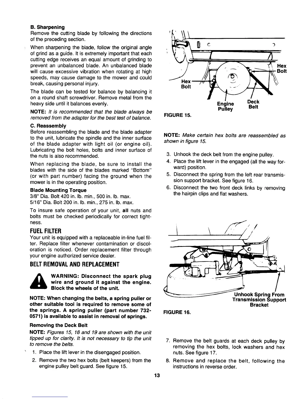
2. Remove the two hex bolts (belt keepers) from the
engine pulley belt guard. See figure 15.
Bolt
FIGURE 15.
Engine Deck
Pulley Belt
NOTE: Make certain hex bolts are reassembled as
shown in figure 15.
3. Unhook the deck belt from the engine pulley.
4. Place the lift lever in the engaged (all the way for-
ward) position.
5. Disconnect the spring from the left rear transmis-
sion support bracket. See figure 16.
6. Disconnect the two front deck links by removing
the hairpin clips and flat washers.
FIGURE 16.
Unhook Spring From
Transmission Support
Bracket
7. Remove the belt guards at each deck pulley by
removing the hex bolts, lock washers and hex
nuts. See figure 17.
8. Remove and replace the belt, following the
instructions in reverse order.
13
 Loading...