4. MACHINE ADJUSTMENT:
(a) The cutting height may be adjusted by changing belts on the YR-36, YR-42, YR-48, YR-60
the position of the cutting section carriage and YR-76 only are super HC 3V belts. The
wheels - See Fig. 1. To adjust the front and tension of these belts should be checked as
rear wheels on the YR-42, YR-48, YR-60 and follows:
YR-76 models, remove the entire spindle as- 1. Measure the span length.
sembly and place the spacers either above or 2, At the center of the span, apply a force
below the mounting sleeve, whichever is desired, with a spring scale (at right angles to the
To adjust the rear wheels on the YR-36 model, span as shown in Fig. 3) large enough
remove the bolts that hold the whee! brackets to deflect the belt 1 /64 inch per inch of
to the frame. Position the bracket as desired, span.
then replace and secure bolts. Front wheel 3, The force should be within the range given . .
adjustment on the YR-36 is with spacers, as the below for a properly tensioned drive.
other models. The adjustments maybe graduated 0,0, of small sheave Tension in Ibs.
in increments of half inches or inches as shown 2V2 inch to 4V2 ,.,.3 to 4V2 Ibs, .-
in Fig. 1, 43/4 inch to 6 4 to 6 Ibs.
UPPER IDLER.
SET SCRE~§ ENGINE PULLEY
--=-=
--
-~--
---
LOWE~ IDLE
SSION Pu LLEY
FIGURE 2
I
I
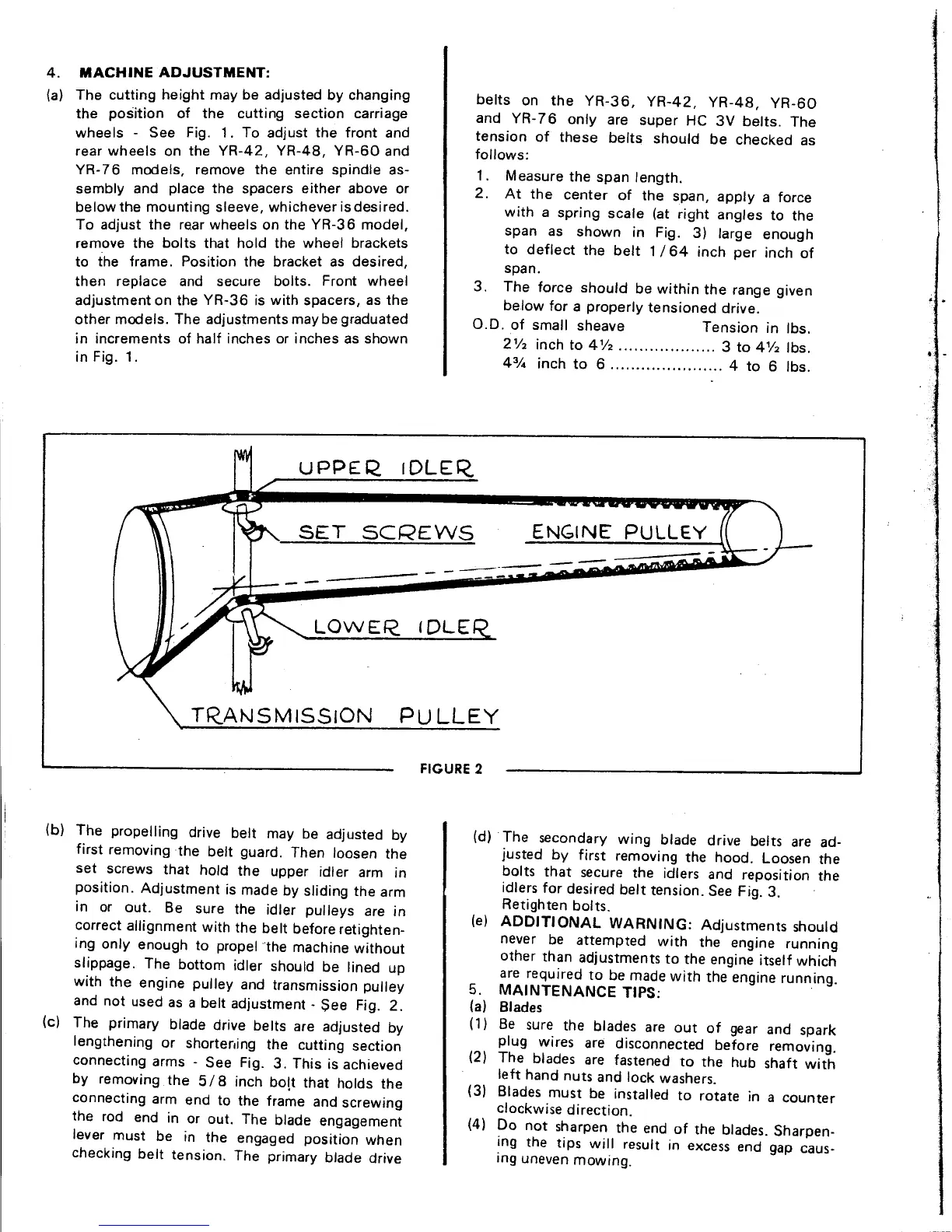
I (b) The propelling drive belt may be adjusted by (d) The secondary wing blade drive belts are ad-
first removing the belt guard, Then loosen the justed by first removing the hood. Loosen the
set screws that hold the upper idler arm in bolts that secure the idlers and reposition the
position. Adjustment is made by sliding the arm idlers for desired belt tension. See Fig. 3.
,
B h .
dl II ' Retighten bolts.
In or ou~. e sur,e tel er pu eys, are In (e) ADDITIONAL WARNING: Adjustments should
~orrect allignment with the ~elt befor~ retl~hten- never be attempted with the engine running
Ing only enough to propel the machIne without other than adjustments to the engine itself which
slippage. The bottom idler should be lined up are required to be made with the engine running.
with the engine pulley and transmission pulley 5, MAINTENANCE TIPS:
and not used as a belt adjustment - $ee Fig. 2. (a) Blades
(c) The primary blade drive belts are adjusted by (1) Be sure. the blad~s are out of gear and s~ark
lengthening or shorterling the cutting section plug wires are disconnected before removing.
t'
S F'
3 Th'. h" d (2) The blades are fastened to the hub shaft with
connec Ing arms - ee Ig. . IS IS ac leve
I ft h d t d I k h" e an nu s an oc was ers.
by removing the 5/8 Inch bolt that holds the (3) Blades must be installed to rotate in a counter
connecting arm end to the frame and screwing clockwise direction.
the rod end in or out. The blade engagement (4) Do not sharpen the end of the blades. Sharpen-
lever must be in the engaged position when ing the tips will result in excess end gap caus-
checking belt tension, The primary blade drive ing uneven mowing.
 Loading...