Shi fter Sleeve
i
Forward Clutch
R Forward Gear
,
I
j c ..
;"C'"i£~
; .
~
'\
~'"
l'
"
j
Screw Driver #1
..
j
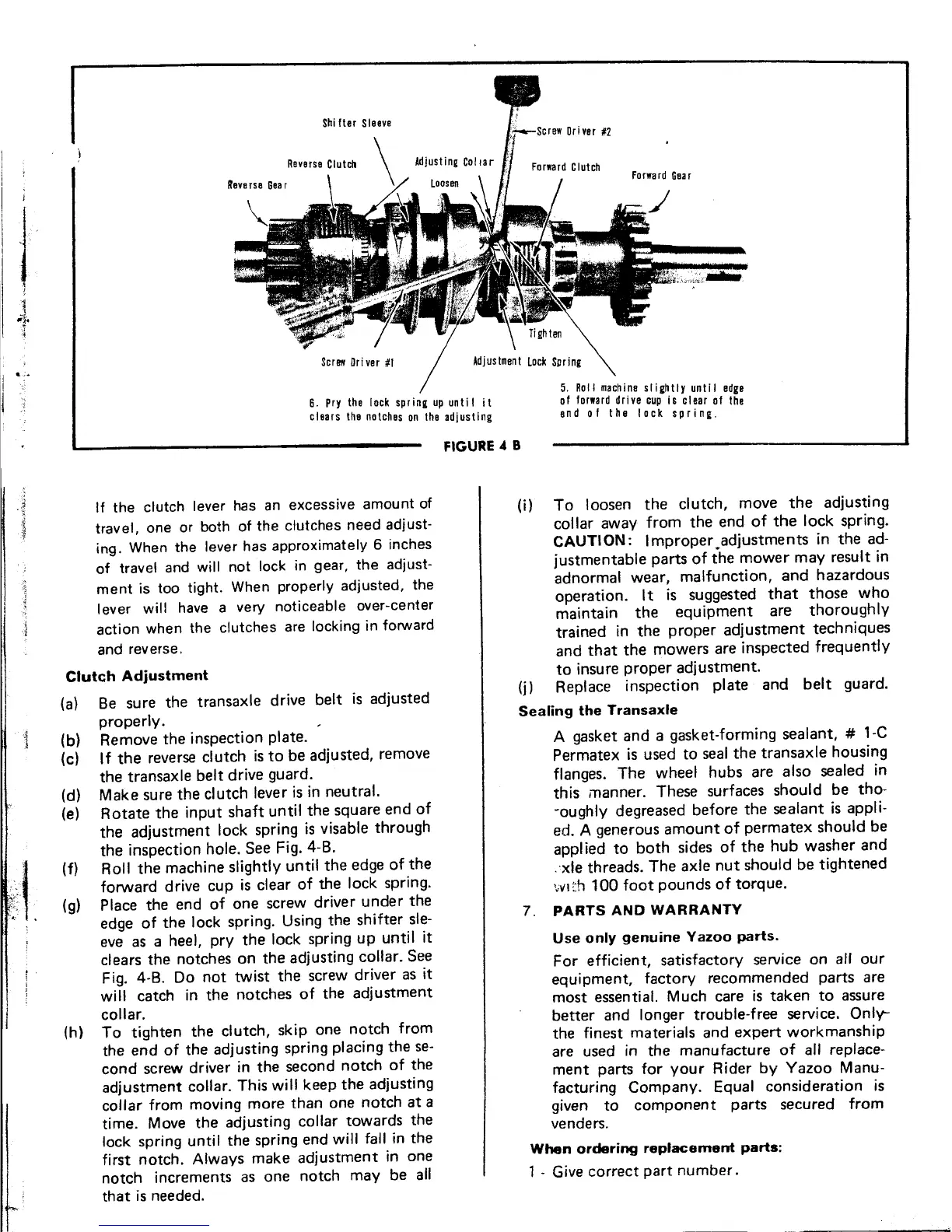
I, 5. Roll machine slightly until edge
6. Pry the lock spring up unti lit of forward drive cup is clear of the
clears the notches on the adjusting end 0 f the lock sp ring
FIGURE 4 B
If the clutch lever has an excessive amount of (i) To loosen the clutch, move the adjusting
travel, one or both of the clutches need adjust- collar away from the end of the lock spring.
ing. When the lever has approximately 6 inches CAUTI ON: Improper #adjustments in the ad-
of travel and will not lock in gear, the adjust- justmentable parts of the mower may result in
ment is too tight. When properly adjusted, the adnor~al wear~ malfunction, and hazardous
.' operation. It IS suggested that those who
lev~r will have a very notlceabl~ o~er-center maintain the equipment are thoroughly
action when the clutches are locking In forward trained in the proper adjustment techniques
and reverse, and that the mowers are inspected frequently
Clutch Adjustment to insure proper adjustment.
.
I . d. d (j) Replace inspection plate and belt guard.
(a) Be sure the transaxle drive be t IS a juste
properly. Sealing the Transaxle
1 (b) Remove the inspection plate. A gasket and a gasket-forming sealant, # 1-C
(c) I f the reverse clutch is to be adjusted, remove Permatex is used to seal the transaxle housing
the transaxle belt drive guard. flanges. The wheel hubs are also sealed in
(d) Make sure the clutch lever is in neutral. this manner. These surfaces should be tho-
(e) Rotate the input shaft until the square end of ~oughly degreased before the sealant is appli-
the adjustment lock spring is visable through ed. A generous amount of permatex should be
the inspection hole. See Fig. 4-B. applied to both sides of the hub washer and
',; (f) Roll the m~chine sl~ghtly until the edge of .the .'xle threads. The axle nut should be tightened
~\: forward drive cup IS clear of ~e lock spring. '~l/lrh 100 foot pounds of torque.
:';:, (g) Place the end of on~ scre~ driver u~der the 7. PARTS AND WARRANTY
edge of the lock spring. Using the shlfter sle-
eve as a heel, pry the lock spring up until it Use only genuine Yazoo parts.
cI~ars the notches on. the adjusting c,:>llar. Se.e For efficient, satisfactory service on all our
FI,g. 4-B. °.0 not tWiSt the screw dr~ver as It equipment, factory recommended parts are
will catch In the notches of the adjustment most essential. Much care is taken to assure
colla~.. better and longer trouble-free service. Only-
(h) To tighten the cI.utc~, skiP. one n,:>tch from the finest materials and expert workmanship
the end of the adjustIng spring placing the se- are used in the manufacture of all replace-
cond screw driver in the second notch of ~he ment parts for your Rider by Yazoo Manu-
adjustment collar. This will keep the adjusting facturing Company. Equal consideration is
collar from moving more than one notch at a given to component parts secured from
time. Move the adjusting collar towards the venders.
lock spring until the spring end will fall in the .
first notch. Always make adjustment in one When ordering replacement parts:
notch increments as one notch may be all 1 - Give correct part number.
that is needed.
---
 Loading...