,~
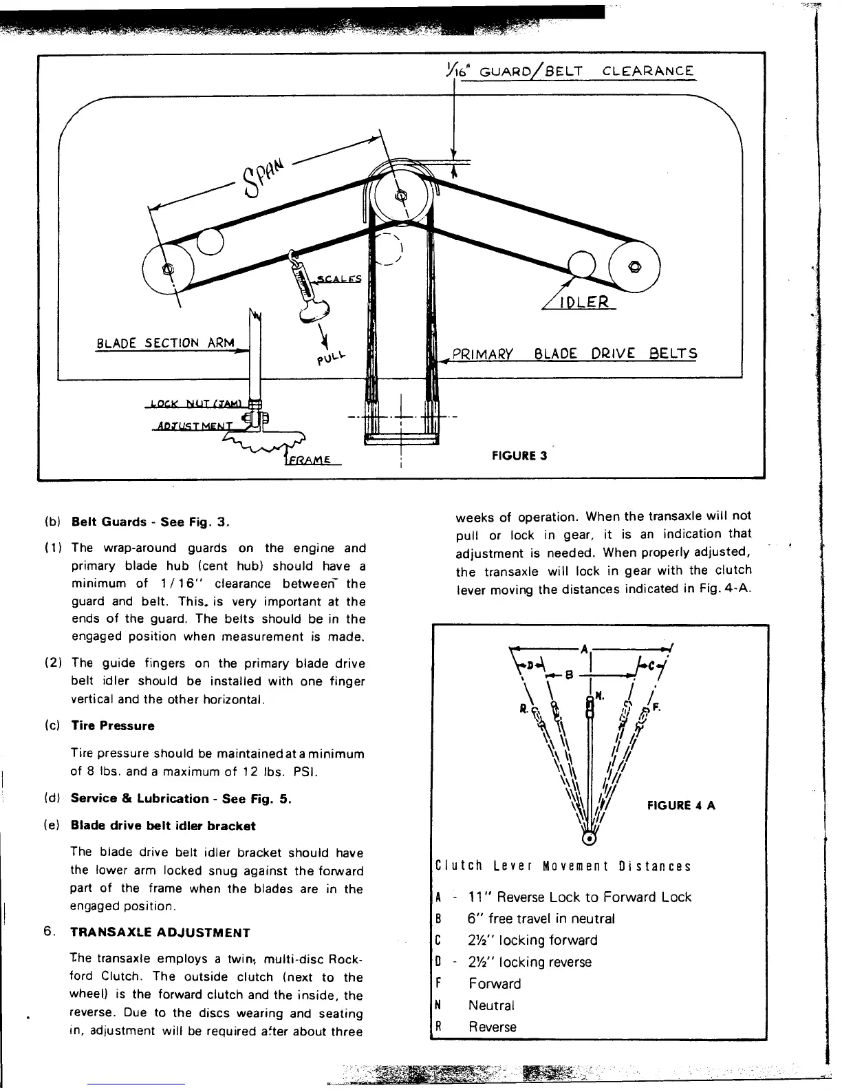
.Y'Io" GUARD/BELT CLEARANCE
,)
.
BLADE SECTION ARM f\)\...\... PRIMARY BLADE DRIVE 8ELTS
-- .1. .-
,
E ' FIGURE 3
I
. weeks of operation. When the transaxle will not
(b) Belt Guards - See Fig. 3, .. ...
pull or lock in gear, It IS an Indication that.
(1) The wrap-around guards on the engine and adjustment is needed. When properly adjusted,
primary blade hub (cent hub) should have a the transaxle will lock in gear with the clutch
minimum of 1/16" clearance between- the lever moving the distances indicated in Fig. 4-A.
guard and belt. This. is very important at the
ends of the guard. The belts should be in the
engaged position when measurement is made. A ~I
(2) The guide fingers on the primary blade drive ";;~~~-=-_l___~-. ;'C1'
belt idler should be installed with one finger \
\ \ e I I'
vertical and the other horizontal. R
, H, ,c~ iF.
. ,~ ,.!I (I:
(c) Tire Pressure \ ~ ff /;1/
T.
b .. d . . \'\ ~
\\ l~ "
,"
Ire pressure should e malntalne at a minimum \~ ~ ~ t
of 8 Ibs. and a maximum of 12 Ibs. PSI. ~\X\ If/,;1
\~\ 1//
(d) Service 81 Lubrication - See Fig. 5. \~\ It! FIGURE 4 A
~ 1/
(e) Blade drive belt idler bracket
.
The blade drive belt idler bracket should have
th I I k d . t th fo d Clutch Lever Movement Distances
e ower arm oc e snug agalns e rwar
part of the frame when the blades are in the A - 11 " Reverse Lock to Forward Lock
engaged position. .
B 6" free travel In neutral
6. TRANSAXlE ADJUSTMENT C 2Y2" locking forward
"the transaxle employs a twin~ multi-disc Rock- D - 2Y2" locking reverse
ford Clutch. The outside clutch (next to the F Forward
wheel) is the forward clutch and the inside, the N
N I
'. eutra
, reverse. Due to the discs wearing and seating
in, adjustment will be required a~ter about three R Reverse
""," ~:~~~1(~::~..", -
 Loading...