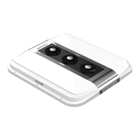
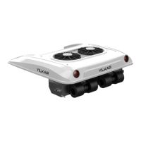
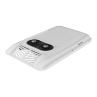
The YILKAR YK 300 is an innovative roof-top air conditioner designed for 9-meter buses, providing thermal comfort to passengers through a vapor compression refrigeration cycle. This monoblock unit is easy to install and integrates a condenser and two evaporators (right and left). It connects to a compressor via hoses for R134a refrigerant circulation. Its aerodynamic design minimizes vehicle height increase (only 27 cm), thereby reducing air resistance and fuel consumption. The YK 300 can operate in outdoor conditions up to 45°C and offers a cooling capacity of 20-30 kW (68242-102364 BTU/h or 17196-25795 kcal/h). Optionally, it can include a heating function by utilizing the waste heat from the vehicle's engine, which also contributes to more effective engine cooling.
Technical Specifications:
- Compressor: BOCK FK40X/470K-560K
- Oil Type/Amount: PAG 100 oil / 2 liters
- Refrigerant/Amount: R 134a / 5000 ± 500 gr
- Evaporator Fan Flow Rate: 4800 m³/h (for 4 Blower Motors)
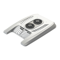
- Condenser Fan Flow Rate: 6600 m³/h (for 3 Axial Fans)
- Pressure Switch: Low pressure: 0.5-1.5 bar; Fan Control: 13-16 bar; High pressure: 21.5-28.5 bar
- Dimensions (Width x Length x Height): 2080/1930/1780 * 1990 * 270 mm (Width is optional according to vehicle roof)
- Weight (Without Mounting Kit): 150 kg
- Maximum Total Electricity Intake: 85 A @ 24 VDC
- Supply Voltage (Control Unit): 12 V - 24 V
- Average Electrical Consumption (Control Unit): 400 mA @ 12V @ 25°C
- Operating Temperature (Control Unit): -10°C to +40°C
- Hoses: 7/8" and 1 1/8" in compliance with SAE-J 2064 TYPE-B CLASS 1 standards. Minimum bending radius: 155 mm for 7/8" hose, 190 mm for 1 1/8" hose.
Components:
The system comprises several key components:
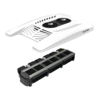
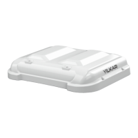
- Fiber Cover: Made of fiber material, it protects the condenser unit on the vehicle roof.
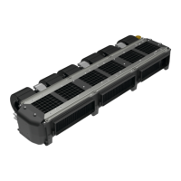
- Condenser: Converts high-pressure R134a refrigerant gas from the compressor into liquid by releasing heat to the environment.
- Evaporator: Evaporates the R134a refrigerant from the condenser, cooling the ambient air.
- Valve: Facilitates phase change by reducing refrigerant pressure.
- Compact Filter: A filter system located at the condenser outlet, trapping impurities and moisture.
- Compressor: Pumps and compresses R134a gas, increasing its pressure.
- Relay Board: Switches current paths on/off based on system voltage and current, ensuring regular operation.
- Air Conditioner Hoses: Circulate R134a refrigerant between components.
Installation:
Installation involves several steps:
- Unit Location: Determine the central line on the vehicle for unit placement according to mounting criteria.
- Hole Drilling: Mark and drill holes on the roof based on the provided technical drawing and unit dimensions. Ensure no electrical cables are present in drilling areas and disconnect the vehicle's battery beforehand.
- Roof Insulation: After cutting the roof, insulate it with 10 mm armaflex material according to specified dimensions.
- Unit Lifting: Lift the YK 300 unit using designated holes and carefully transport it to the vehicle roof, ensuring secure connections to avoid accidents.
- Cover Removal: Before final installation, remove the right, left, and middle covers of the air conditioner.
- Mounting: Secure the unit to the roof using 12 bolts, passing them under the roof and tightening with washers and nuts over the unit.
- Sealing: Apply SIMSON ISR 70-03 white sealant around the unit's base and between the condenser and evaporator sections (after opening the grids) for insulation.
- Hose and Fitting Mounting:
- Cut hoses straight.
- Lubricate the inner part of the hose where the union will pass.
- Tighten hose couplings to the hose with a wrench.
- Tighten hose-pipe coupling assembly to the union.
- Protect hoses from internal/external factors, moving elements, and hot parts. Isolate them from sharp edges and corners. Bend hoses to their minimum bending radius.
- Secure hoses to the vehicle with cable ties after all connections.
- For water discharge, tighten clamps behind the evaporator's water discharge section. Ensure drain hoses are inclined at least 2° to prevent water obstruction.
- Electrical Connections:
- Control Unit Mounting: Choose an ergonomic flat surface accessible to the driver (90x45 mm dimensions). Cut the surface, then mount the control unit using nails. Assemble control panel sockets to the unit, checking locks.
- Fuse Box: Place an 80A fuse. Connect the 16 mm B+ cable (M6 end to fuse, M8 end to battery's (+) terminal). Connect another 16 mm B+ wire (M6 end to fuse, M8 end to relay board's (+) pole).
- Cabinet Assembly: Attach nuts with M5 washers.
- Signal Connection: Connect the D+/ACC signal from the vehicle's alternator to cable 1 via single sockets.
- Fiber Cover Assembly: After all installations, reattach the right, left, and middle covers. Secure them with M6x25 bolts with torque head washers.
Commissioning:
- Leakage Control: Pressurize the system with Nitrogen (20 bar) and check for air bubbles at connections using soapy water.
- Vacuuming: Vacuum the system for at least 30 minutes using a vacuum pump connected to the compressor to remove air and moisture before refrigerant charging.
- Gas Charge: Charge the system with R134a gas according to the amount specified in the technical data.
- Operation: Start the vehicle and operate the air conditioner from the control panel.
Control Unit Overview and Operation:
The digital controller activates/deactivates the air conditioner based on automatically adjusted set values from temperature probes.
- Buttons: Increase/decrease set temperature, change fan speed, open/close (flap), heating on/off (optional).
- Display Screen: Shows set temperature, outside temperature, inside temperature, cooling/heating/ventilating mode indicators (snowflake for cooling, wavy lines for heating), and fan speed.
- Cooling Mode: Press the cooling button. Snowflake sign appears on screen.
- Heating Mode (Optional): Press the heating button. Wavy lines sign appears on screen.
- Ventilating Mode: Press the fan stage button. No snowflake or heating sign appears on screen.
Fault Codes (Control Unit):
- E1: Inside Temperature Sensor Open Circuit:
- Cause: Cut cable, disconnected socket, or faulty sensor.
- Device Response: System shuts down, error code displayed.
- Troubleshooting: Check cable/sockets; replace sensor if no issues found.
- E2: Outside Temperature Sensor Open Circuit:
- Cause: Cut cable, disconnected socket, or faulty sensor.
- Device Response: System shuts down, error code displayed.
- Troubleshooting: Check cable/sockets; replace sensor if no issues found.
Usage and Maintenance Recommendations:
- Routine Maintenance: Perform regularly to improve operation.
- Battery Disconnection: Disconnect the vehicle's battery before opening the air conditioner cover for maintenance.
- Electrical Protection: Protect electrical components during cleaning. Inspect all system components at the start of each season.
- Compressor Belt: Check tension twice a year; replace if old.
- Heat Exchangers: Be careful of pointed fin ends to avoid injury.
- Condenser Cleaning: Crucial for performance. Clean frequently, especially in dusty environments, to remove insects, feathers, and debris that reduce heat exchanger effectiveness and shorten compressor life. Use compressed air without damaging aluminum fins.
- Condenser Electric Fans: Inspect operation. One fan starts with the AC, the second activates when temperature rises via the control switch.
- Dust Filters: Regularly clean dust filters in the exterior air intake chamber and driver's compartment.
- Extended Inactivity: Run the unit for half an hour at least once a month, even in winter, to lubricate components and prevent drying out.
- Dryer Replacement: Recommended during major repairs or if the system has been inactive for a long time or has internal moisture.
- Refrigerant Operations: All repairs, filling, or discharging of refrigerant gas must be done by experienced personnel at authorized auto air conditioner garages.
- Refrigerant Type: Uses R134a refrigerant.
- Vehicle Windows/Doors: Keep closed while the air conditioner is operating.
- Post-Installation Inspection: Perform a general inspection 1500 km after installation, especially checking compressor and fastener tightness.
Spare Parts Ordering:
When ordering spare parts, provide:
- Full address
- Photocopy of vehicle's license
- Desired shipping format
- Full description of the unit and serial number
- Part number and amount of requested spare part.
Only use original YILKAR approved spare parts; unauthorized parts void the warranty and may affect safety and operation.