8600
9500
7800
Frequency(Hz) (High/Standard/Low)
70/41/15
63/44/15
80/57/15 75/65/15 100/60/15 100/60/15100/60/15
Nominal heating capacity (ID 70/60 OD 47/43F)
Standard Set-up Tested in Lab-Heating capacity (ID 70/60 O D17/15F)
Standard Set-up Tested in Lab-Heating capacity (ID 70/60 O D 5F)
11000
13000
8900
16400
25000
14500
17800
26000
15400
24800 31600
26500 34600
21200 26800
100/60/15
Conne-
ction
Pipe (In)
oo
15FT115F
oo
5FT86F
Outdoor
Unit
(ODU)
Starting Method
o
Recommended Working Ambient Temp Range (F)
Condenser Coil Type
Coil-Copper Pipe Diameter (In)
Rows-FPI
Coil Length (L) x Height (H) x Depth (D) (In)
Fan Motor Speed (rpm) (H/L)
Output of Fan Motor (W)
Fan Motor RLA (A)
Fan Motor Capacitor (uF)
Air Flow Volume of Outdoor Unit CFM
Fan Type-Piece
Fan Diameter (In)
Defrosting Type
Designed for Climate Type
Isolation
Moisture Protection
Sound Pressure Level dB (A) (H/M/L)
Sound Power Level dB (A) (H/M/L)
0.28
2-18.2
Transducer starting
Aluminum fin-copper tube
23.9X20.0X1.7
900/650
900 20
40
0.17
(DC)
1120
Axial-1 Axial-1 Axial-1 Axial-1
15.7
Auto defrost
T1
I
IP24
551
174
53
63
Transducer starting
Aluminum fin-copper tube
29.4X20X1.7
900/680
900 20
40
0.17
1120
15.7
Auto defrost
T1
I
IP24
551
174
55
65
0.35
Transducer starting
oo
15FT115F
oo
5FT86F
Aluminum fin-copper tube
0.28 0.28 13/16 3/8
33.0x26.0x1.5
690/500
60
0.62
3
1890
20.5
Auto defrost
T1
I
IP24
551
174
54
64
Transducer starting
Aluminum fin-copper tube
38.1x29.4x1.5 37.5x29.5x1.5 37.0x30.0x1.7
780/500 830 830
90 90 120
0.90 0.45 0.45
4 5 5
2480
21.7 21.75 21.75
Auto defrost
T1
I I
IP24 IP24
551 560
174 170
56
66
oo
15FT115F
oo
5FT86F
oo
15FT115F
oo
5FT86F
MAX. Operating Pressure for the Discharge Side (PSIG)
MAX. Operating Pressure for the Suction Side (PSIG)
Liquid Pipe (In)
Gas Pipe (In)
ID Above/Blow OD (Ft.)
Length (Ft.)
Outer Diameter
Max Distance
25
1/4
3/8
70
25 25
1/4 1/4 1/4
3/8
75
25
1/2 5/8
100 100
(DC)
Air Flow Volume (CFM) (SH/H/M/L)
300/277/253/218
500/460/383/324
560/471/412/353
Indoor
Unit
(IDU)
WMMS-09E-V2A/B(58) (2)
1300/1060/920/740 1320/1200/1100/960
WMMS-12E-V2A/B(58) (2)
1300/1080/900/740 1300/1160/1040/920
WMMS-18E-V2B(58) (2) WMMS-24E-V2B(58) (2)
1350/1200/1050/900
1420/1250/1150/1050
Dehumidifying Volume (Pints/Hr.)
1.7
2.5 4.2
5.5 6.3 7.4
1400/1150/1100/850 1400/1150/1100/900
Model of Indoor Unit
Fan Motor Speed (RPM) (SH/H/M/L)
Output of Fan Motor (w)
Input of Heater (w)
Fan Motor Capacitor (uF)
Fan Motor RLA(A)
Fan Type-Piece
Fan Wheel Diameter-Length (In)
Evaporator Coil Type
Coil-Copper Pipe Diameter (In)
Row-FPI
Coil length (L) x Height (H) x depth (D) (In)
Swing Motor Model
Output of Swing Motor (W)
Fuse (A)
Sound Pressure Level dB (A) (SH/H/M/L)
Sound Power Level dB (A) (SH/H/M/L)
Model of Outdoor Unit
Compressor Manufacturer
Compressor Model
Compressor Type
L.R.A. (A)
Compressor RLA(A)
Compressor Power Input(W)
Overload Protector
Throttling Method
20
/
4.0 / 1.0
0.38 / 0.20
Cross flow fan-1
3.6 X 25.4
Aluminum fin-copper tube
0.28
2-18.2
25.4X1X10.5 25.4X1X10.5
MP24AA
2.4
PCB 3.15A
38/34/30/26
48/44/40/36
WMMS-09C-V2A/B(58) (2)
SANYO / MITSUBISHI
C-6RZ110H1A
Twin Rotary DC Twin Rotary DC Twin Rotary DC Twin Rotary DC
33
4.59
800
Electronic Expansion Valve
WMMS-18C-V2B(58) (2) WMMS-24C-V2B(58) (2)WMMS-12C-V2A/B(58) (2)
3.6 X 25.4
20
/
4.0 / 1.0
0.38 / 0.20
Cross flow fan-1
Aluminum fin-copper tube
MP24AA
2.4
PCB 3.15A
40/36/32/26
50/46/42/36
SANYO / MITSUBISHI
C-6RZ110H1A
33
4.59
800
Electronic Expansion Valve
0.28
2-18.2
20
/
1.5
0.25
Cross flow fan-1
3.9 X 28.0
Aluminum fin-copper tube
0.28
28.1X12X1
MP28VB
2.5
PCB 3.15A Transformer 0.2A
46/44/40/35
56/54/50/45
SANYO / MITSUBISHI
SANYO / MITSUBISHI
C-6RZ146H1A
41
8.4
1640
1NT11L-3979
1NT11L-39791NT11L-3979
Electric Expansion Valve
EER (Btu/h.w)
14.0
12.5
12 12
Rated Current (A) (High/ Standard)
SEER / HSPF (Btu/h.w)
A:13.5/7.0 B:6.5/3.2
22
A:14.5/7.5 B:6.8/3.5
9.8
A:14.5/11 B:7.0/5.2
20
A:15.5/12.5 B:7.5/6.0
9.6
13.2/8.6 17.2/12.4 17.4/12.7 18.2/15.1 18.2/15.512.7/8.2
System Model
Functions
Power Soure
COOLING
208~230/1/60
HEATING
WMMS-24K-V2B(58) (2)
COOLING
A:115/1/60 B:208~230/1/60
HEATING
WMMS-09K-V2A/B(58) (2)
COOLING
A:115/1/60 B:208~230/1/60
HEATING
WMMS-12K-V2A/B(58) (2)
COOLING
208~230/1/60
HEATING
WMMS-18K-V2B(58) (2)
12.56/7.712.0/7.5
Power Input (W) (High/ Standard/Low)
1050/660/180 1100/700/220 1450/1000/120 1500/1200/220 2750/1790/500
3450/2780/550 3500/2370/700 3800/3650/610 3700/3560/970
2650/1700/400
2550/1600/3352500/1500/300
18.0
10.2
18.0
35
/
2.5 3.5 3.5
0.45
Cross flow fan-1
3.9 X 30.1 4.25 X 41.0 4.25 X 41.0
Aluminum fin-copper tube
0.28
30.1X13.5X1 42.25X15X1 42.25X15X1
MP35XX MP24BA MP24BA
2.5
PCB 3.15A Transformer 0.2A
48/44/40/35
58/54/50/45
C-6RZ146H1A
TNB220FLHMC
41 45 67
8.4
1640 2200 3010
1NT11L-3979 CS01F272H01 CS01F272H01
Electric Expansion Valve
A:30 B:20 20
30 30 40
Fuse Circuit Breaker of HVAC Type
35/45 35/45
50/60 50/60
2-18.2 2-16.9 2-19 2-19
2-18.2 2-18.2 2-18.2 2-1.4 2-1.4
WMMS-30K-V2B(58) (2) WMMS-36K-V2B(58) (2)
WMMS-30E-V2B(58) (2) WMMS-36E-V2B(58) (2)
HEATING
COOLING
HEATING
COOLING
208~230/1/60 208~230/1/60
58/-/56
68/-/66
59/-/57
69/-/67
Capillary Capillary
oo
5FT86F
oo
15FT115F
oo
5FT86F
oo
15FT115F
Transducer starting Transducer starting
Aluminum fin-copper tube Aluminum fin-copper tube
Axial-flow Axial-flow
T1 T1
1/4 1/4
5/8 5/8
I
IP24
560
170
Automatic Defrosting Automatic Defrosting
WMMS-30C-V2B(58) (2) WMMS-36C-V2B(58) (2)
MITSUBISHI MITSUBISHI
125 125
25 25
2860 2860
50/60 50/60
/
Cross flow fan-1
Aluminum fin-copper tube
0.28
2 2
PCB 3.15A Transformer 0.2A PCB 3.15A Transformer 0.2A
52/50/48/40 52/50/48/40
62/60/58/50 62/60/58/50
Aluminum fin-copper tube
0.28
Cross flow fan-1
/
16 168.2 8.2
10 9.2
740/670/640/580 740/670/640/580
40
0.4 0.4
40
TNB306FPGM
Rotary DC Rotary DC
9.7 13.5
1400/1300/1200/1000 1400/1300/1200/1000 1400/1300/1200/1000 1400/1300/1200/1000
Total Capacity (Btu/h) (High/ Standard/Low)
10600/9000/4435 11100/9500/3200
14000/12000/4500
14500/13000/3250
26000/25600/1120025000/21500/960025000/19000/4100
22350/18000/6000
30000/28000/7400 33000/28500/10000 36000/33600/9500 36000/34600/15000
10.2
A:30 B:20
Dimensions-Net W x H x D (Inches)
Dimensions-Net W x H x D (Inches)
Dimensions of Carton Box W x H x D (Inches)
Gross / Net Weight (LBs)
Dim. &
Weight-
Indoor
Unit
33.3 x 10.8 x 7.1 33.3 x 10.8 x 7.1
36.0 x 14.0 x 10.0 36.0 x 14.0 x 10.0
31/24
31/24
37.0 X 11.7 X 7.9
39.8 X 15.0 X 11.2
37.5/28.7
39.7 X 12.4 X 8.6
42.2 X 15.6 X 12.3
46.3/35.3
Gross / Net Weight (LBs)
Dim. &
Weight-
Outdoor
Unit
33.4 x 21.3 x 12.6
34.6 x 22.8 x 14.2
90/79
33.4 x 21.3 x 12.6
34.6 x 22.8 x 14.2
97/88
Assumed-One Model/ContainerSets (20'/40'/40'HQ)
Safety Approval (Third Party)
Performance Approval (Third Party)
Container
Loading
Certification
109/232/252
ETL (C & US)
AHRI / Energy Star
109/232/252 60/125/145 47/96/114
ETL (C & US) ETL (C & US) ETL (C & US)
AHRI / Energy Star AHRI / Energy Star AHRI / Energy Star
35.0 X 27.6 X 13.4
40.6 X 28.9 X 18.1
121/110
36.2 X 31.1 X 14.6
41.9 X 33.1 X 19.0
132/119
36/75/92 36/75/92
60/4460/44
170/161163/155
38.5 X 31.3 X 16.8 38.5 X 31.3 X 16.8
42.5 X 33.3 X 19.3 42.5 X 33.3 X 19.3
53.1 X 12.8 X 10.0 53.1 X 12.8 X 10.0
56.6 X 16.5 X 13.5 56.6 X 16.5 X 13.5
ETL (C & US) ETL (C & US)
Dimensions of Carton Box W x H x D (Inches)
AHRI AHRI
330/295/253/218
If Not Marked on Nameplate, Refrigerant
Pre-charged for Copper Line Length
Check Pressure at Trial Running
Add or Deduct Refrigerant
0.28 0.32 0.38
0.32
0.54 0.54
BRIEF UNIT INFO
BRIEF UNIT INFO
P15 OF 38 P16 OF 38
MINI WALL MOUNT SYSTEMS - SPECIFICATION BRIEFS
Unit Specifications and Engineering Submittal
1. Performance rated for matched system at standard conditions-cooling ID 80/67F, OD 95F; heating ID 70/60F, OD 47/43F.
Unit performance varies when weather changes from the standard one.
2. Select equipment capacity sizes per space load calculation schedule and cooling & heating hours. Not to over size or under size equipment.
3. Watch unit operation during extreme weather conditions in summer and winter. baffle helps system cooling & heating performance in
low ambient temperatine ranges.
Wind
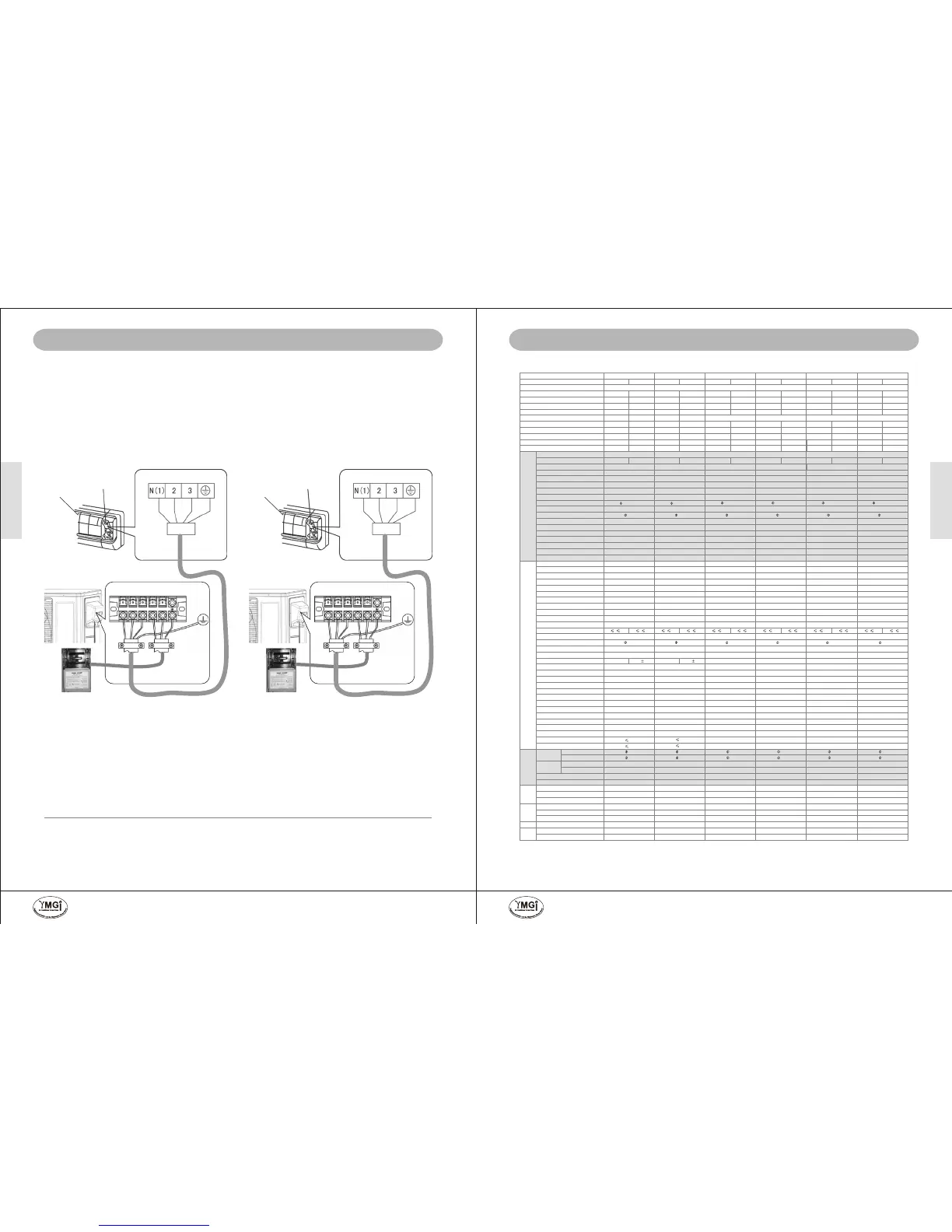
CONNECTION OF WIRES
Front (surface)
Panel
Note:
* The environment conditions must be taken into consideration when the connections of power cable are made
(such as the ambient temperature, direct exposure to heat exposure to sunlight).
* The specifications for the power cable refer to the minimum values of the metal core wires, taking into
consideration the voltage losses, the core wire of power cable must be one size larger than the specifications.
* The grounding wire must be connected to the indoor units and outdoor units.
* The laying of power cables must be done by qualified electricians and comply with the regulations of the local
power supply authorities and with the standards of the electric appliance.
09K/12K Models (115/1/60) 18K/24/30K/36K Models (208~230/1/60)
Wiring Cover
WIRING AT INDOOR UNIT AND OUTDOOR UNITS
* Open the front cover panel.
* Remove screws from electrical box cover and put screws in secured position.
* Remove screws from fastener and put screws in secured position.
* Prepare wires of right size and grade.
* Recommend to use factory-provided wire/cables.
* Connected to the terminals following wiring diagrams (terminal or color matches).
* Clamp power/control wires to the structure to keep the tension form being transmitted to the wire connection.
* Replace screws or fasteners back to where they were.
PIPING AND WIRING SIZES
Model
Liquid/Gas
Line
Min/Max.Length/
+/-Elevation
Power Wire Min.
Disconnect Switch Box to
Outdoor Unit
Power/ Control Wire Min.
Outdoor to Indoor Unit
Recommended HVAC
Circuit Breaker/Fuse
AMP (to Outdoor Unit)
09K
1/4" & 3/8"
15/70 /35/45
L/N/G, 115/1/60, 12AWG
N(1)/2/3/G, 115/1/60, 16AWG
20/30
12K
1/4" & 3/8"
15/75 /35/45
L/N/G, 115/1/60, 12AWG
N(1)/2/3/G, 115/1/60, 16AWG
20/30
18K
1/4" & 1/2"
15/100/50/60
L1/L2/G, 208-230/1/60, 10AWG
N(1)/2/3/G, 208~230/1/60, 16AWG
20
24K
30K
36K
1/4" & 5/8"
1/4" & 5/8"
1/4" & 5/8"
15/100/50/60
15/125/50/60
15/125/50/60
L1/L2/G, 208-230/1/60, 10AWG
L1/L2/G, 208-230/1/60, 8AWG
L1/L2/G, 208-230/1/60, 8AWG
N(1)/2/3/G, 208~230/1/60, 16AWG
N(1)/2/3/G, 208~230/1/60, 16AWG
N(1)/2/3/G, 208~230/1/60, 16AWG
30
30
40
Terminal block of
outdoor unit
(To power supply)
N(1)
2
3
L N
Indoor Unit
Outdoor Unit
Front (surface)
Panel
Wiring Cover
N(1)
2
3
L1 L2
Teminal block
of indoor unit
(To outdoor
unit)
Terminal block of
outdoor unit
(To power supply)
Indoor Unit
Outdoor Unit
Teminal block
of indoor unit
(To outdoor
unit)
Terminal matchTerminal match
YMGI, Engineered Comfort Products for A Sustainable and Efficient Green World !YMGI, Engineered Comfort Products for A Sustainable and Efficient Green World !
 Loading...