Appendix 2. Installation Conditions for CENTUM V and CENTUM-XL
App.2-2
TI 33K01B10-50E
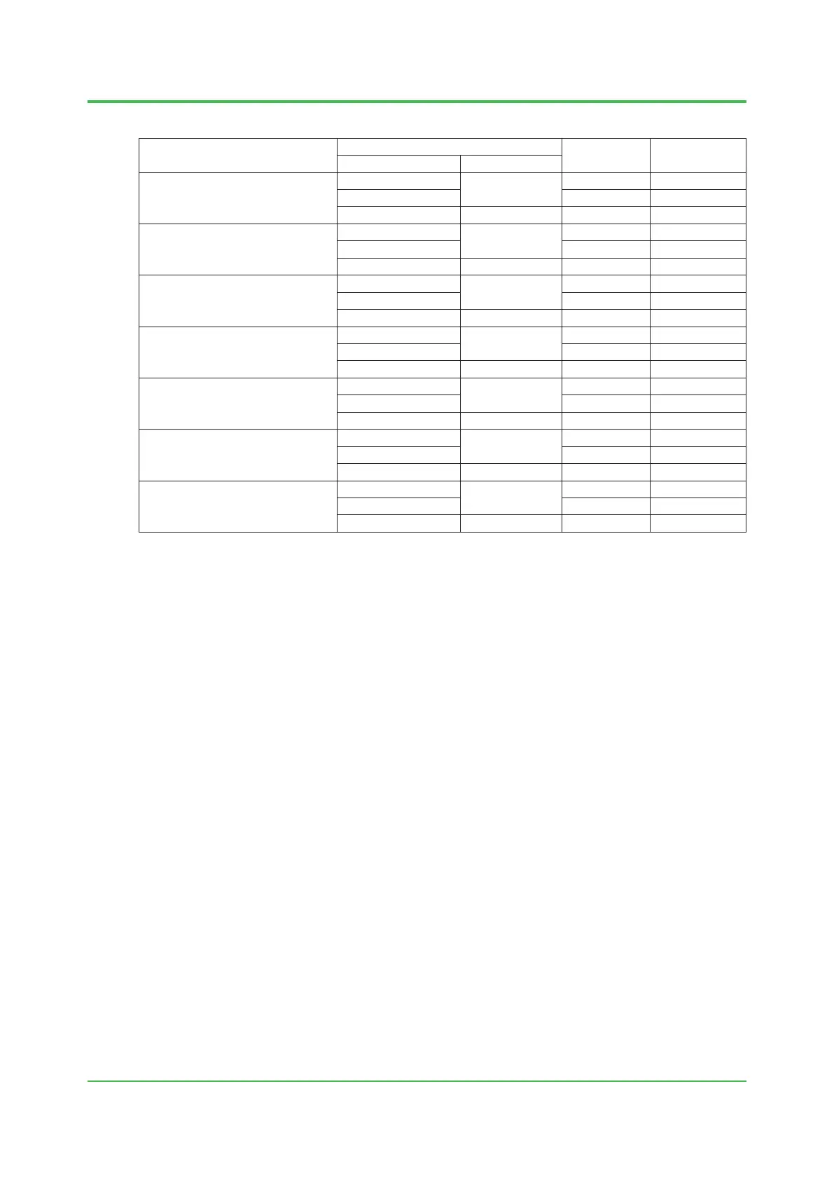
(2) Installation Conditions for CENTUM-XL
Equipment
Input-voltage range
Max. power
consumption
Heating value
(J/h)
Voltage (V) Frequency (Hz)
EFCS-S
Field Control Station
90 to 125 V AC
50/60
1780 VA 3800 x 10
3
198 to 254.4 V AC 2100 VA 4100 x 10
3
24 V DC – 47 A 3900 x 10
3
EFCD
Duplexed Field Control Station
90 to 125 V AC
50/60
1950 VA 4200 x 10
3
198 to 254.4 V AC 2400 VA 4500 x 10
3
24 V DC – 53 A 4400 x 10
3
EFUS
Field Control Unit
90 to 125 V AC
50/60
250 VA 460 x 10
3
198 to 254.4 V AC 250 VA 460 x 10
3
24 V DC – 5 A 420 x 10
3
EFUD
Field Control Unit
90 to 125 V AC
50/60
280 VA 500 x 10
3
198 to 254.4 V AC 280 VA 500 x 10
3
24 V DC – 5.5 A 460 x 10
3
EFMS
Field Monitoring Station
90 to 125 V AC
50/60
910 VA 1900 x 10
3
198 to 254.4 V AC 1050 VA 1900 x 10
3
24 V DC – 16 A 1300 x 10
3
ETBC
Terminal Board Cabinet
90 to 125 V AC
50/60
1760 VA 3800 x 10
3
198 to 254.4 V AC 2250 VA 4000 x 10
3
24 V DC – 48 A 4000 x 10
3
EFGW
Field Gateway Unit
90 to 125 V AC
50/60
170 VA 250 x 10
3
198 to 254.4 V AC 180 VA 250 x 10
3
24 V DC V AC – 3 A
Note: The table shows the power consumption and heat dissipation when the respective components are loaded to the maximum.
Mar. 27, 2015-00
 Loading...
