1. Overview of Vnet/IP
1-14
TI 30A10A05-01E
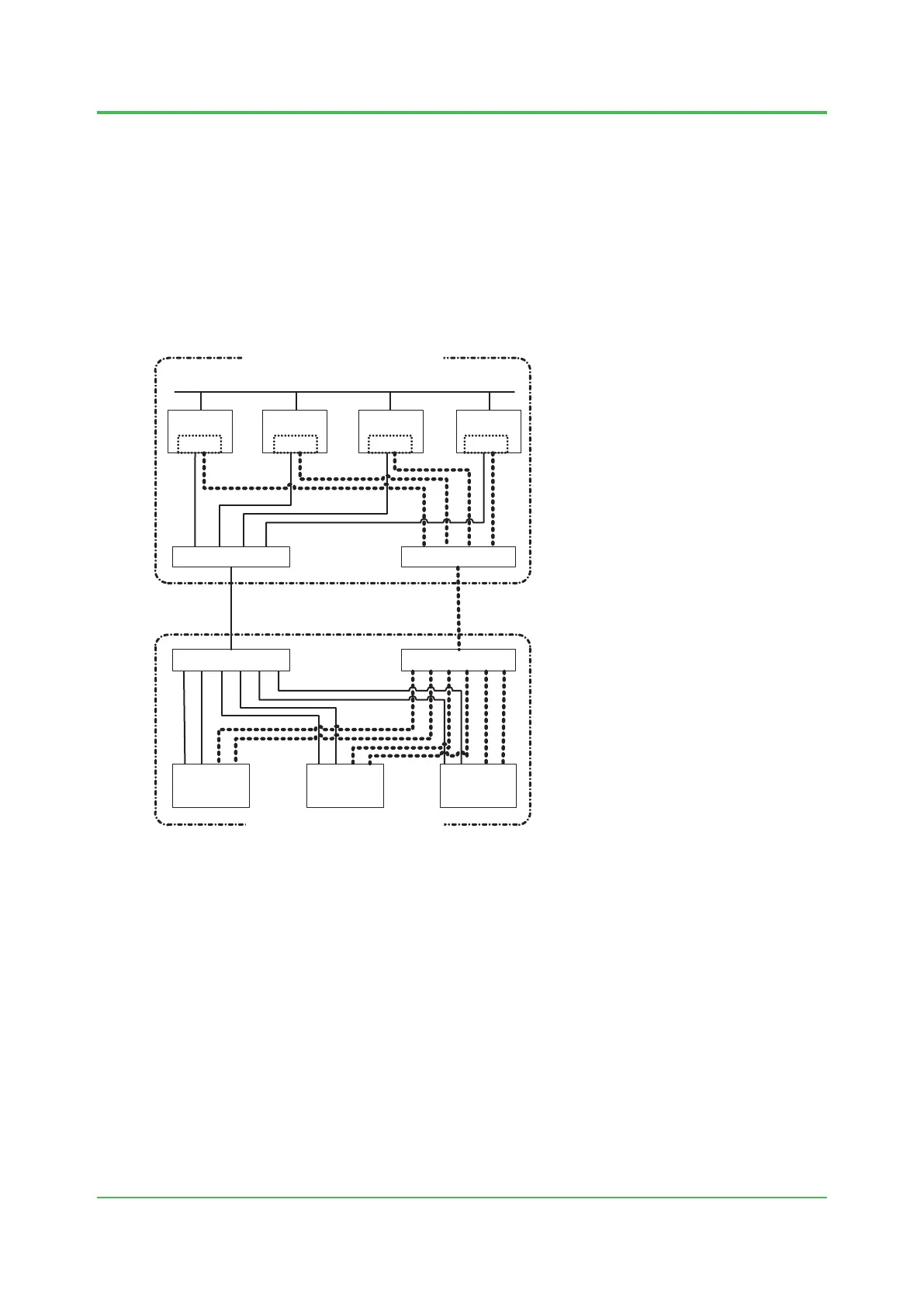
n Connection within a Vnet/IP domain
A dual-redundant Vnet/IP bus consists of independent subnets, bus 1 and bus 2. A Layer 2 switch
is installed in each line.In Vnet/IP stations with dual redundant CPU modules, each CPU module
has ports for bus 1 and bus 2, which connect to layer 2 switches in their respective paths. You
can extend the paths up to 5 km by using optical ber cables between layer 2 switches (*1). From
the operation and maintenance perspective, we recommend that you use the same number of
levels of layer 2 switches and path length for bus 1 and bus 2.
*1: In case further length is required, contact YOKOGAWA for details.
The following gure shows an example of a Vnet/IP domain conguration in which the central
control room is in a dierent location from the control device room.
010402E.ai
HIS 3 SENG
FCS 1
L2SW
HIS1/ENG HIS 2
L2SW
L2SW L2SW
FCS 2 SCS
Bus 1 Bus 2
Location A (Central Control Room)
Location B (Control Device Room)
Information Network
Vnet/IP
Interface Card
Vnet/IP
Interface Card
Vnet/IP
Interface Card
Vnet/IP
Interface Card
Figure ExampleofaVnet/IPDomainConguration
Dec. 26, 2016-00
 Loading...