2.Vnet/IPNetworkConguration
2-14
TI 30A10A05-01E
Dec. 26, 2016-00
2.2.4 ConnectingnetworkswitchesbyRingTopology
n ConguringanetworkusingRingTopology
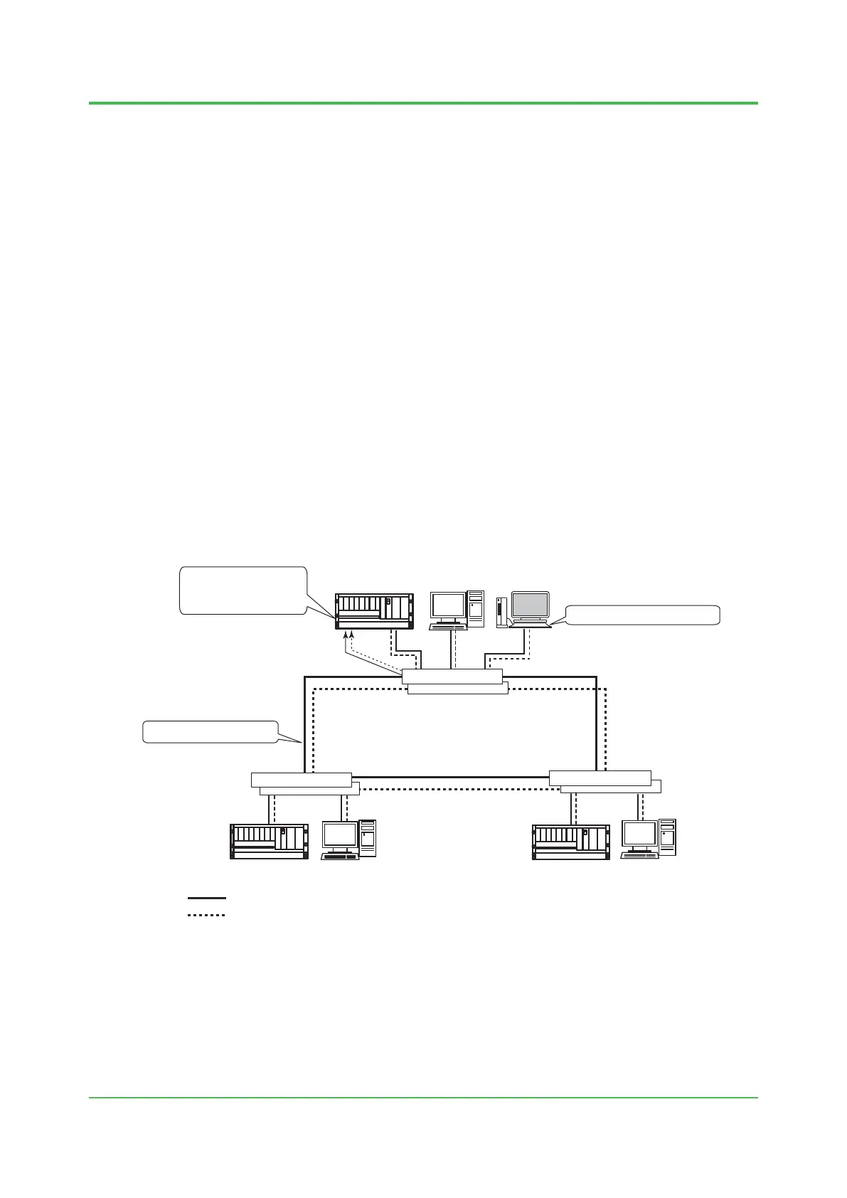
A ring network can be congured by connecting multiple L2SWs in a loop in a Vnet/IP domain.
A system conguration where Vnet/IP network is congured in a ring network is as shown below.
(1) Setting Ring protocol
Ring protocol has to be set to both Bus 1 and Bus 2 of the network switch for Vnet/IP to
make both of the Bus 1 and Bus 2 have ring conguration.
(2) Acknowledgment of occurrence of and recover from failures
The system has to be engineered to generate alarms when ring failures occur as well as
recover from failures. Specically, a signal from a FAULT output terminal of the network
switch assigned as the Ring manager (RM) has to be received by a digital input module of
CENTUM VP’s FCS, and its on/o is to be notied to an HIS.
(3) Identifying failed point
Identication of the failed point in the ring network is done by the network management
system (PMS) in a computer independent from HIS or by manually.
When conguring a ring network, the network has to be segregated by VLAN for security
and prioritize tracs.
F020208E.ai
HIS
FCS
FCSFCS
: Bus 1
: Bus 2
HIS
HIS/ENG
Computer for
ring management
L2SW
L2SW
L2SW
FAULT Signal
(2)
Acknowledgment of
occurrence of and
recovery from failure
Setting Ring protocol
Identifying the failed point
(3)
Figure RingNetworkStructure
Contact Yokogawa for more details about how to congure a network using Ring topology.
 Loading...