4. Appendix
4-11
TI 30A10A05-01E
4.7 Ringnetworkconguration
n AboutRingnetwork
A ring network is a network topology where each network switch connects to two other
switches, forming a communication pathway in a ring. The ring topology provides a redundant
communication path. The advantage of the ring network is that even a failure occurs at a point
on the network, the communication is not disturbed.
n Backgroundofwhyringnetworkisrequiringincontrolnetwork
Vnet/IP has achieved redundancy by isolating the network using bus 1 and bus 2, and the ring
network has not been supported in its standard network structure. However, when the bus 1
and bus 2 cables are routed in the same location, both of the communications break in cases the
place is disturbed by a natural disaster or alike. Control networks are required to be congured in
the ring network of which redundancy is established by having dierent routes.
n Ringnetworkmethod
In order to establish the ring network with Vnet/IP, L2SWs in a domain must be structured in
a ring. Several protocols for redundancy are available to form the ring network; however, the
Media Redundancy Protocol (MRP) is adopted for the Vnet/IP for the following reasons.
• MRP is specied by the international standard of IEC 62439
• Switching of the communication path is performed in high speed
n Structureofringnetwork
The MRP is one of the most versatile protocols relatively easy to form the ring network.
The gure below shows how the ring network performs using the MRP.
F040701.ai
RM
L2SW L2SW L2SW
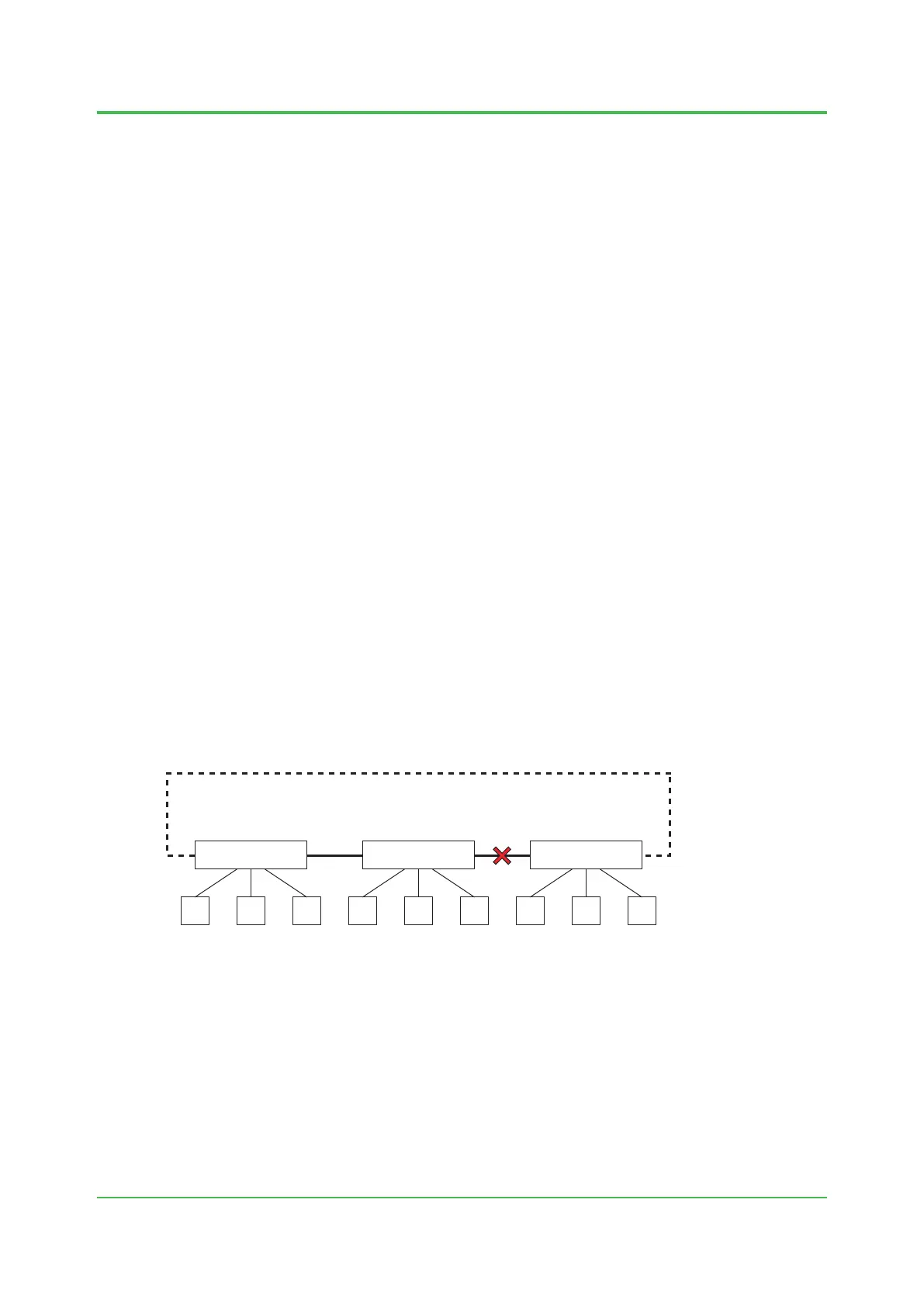
Figure Ringnetwork
The above gure is the ring network using three switches connected in a loop. In the ring
network, Ring Master (RM) which is a switch to manage the ring has to be specied. Under the
normal status, the communication is done through the path shown as the solid line. A port on a
side (i.e. left in this gure) of the RM is disabled and the communication is not performed. When
a failure occurs on the path shown as the solid line, the RM activates the disabled port and the
communication is performed via the broken-line path.
Dec. 26, 2016-00
 Loading...