4-6
IM WT310-02EN
4.4 Displaying Voltages, Currents, and Active
Powers on the WT330
For details, see section 4.1 in the User’s Manual, IMWT310-01EN.
After you select the measurement ranges (the voltage and current ranges), select the measurement
items that you want to show in each display.
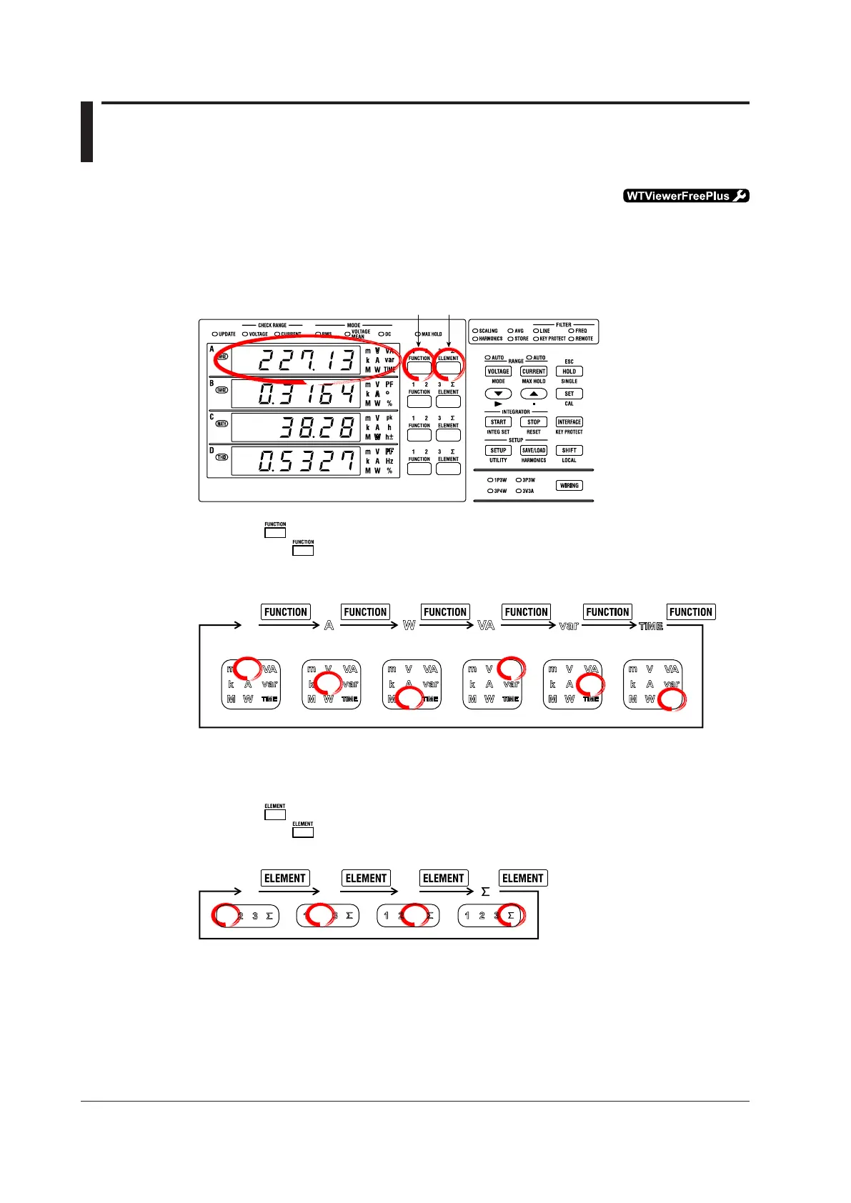
Displaying a Voltage in Display A on the WT330
Function key Element key and indicators
1.
Press the key for display A, and select V.
When you press , the function and unit indicators for display A light in the following order. To display a
voltage on display A, press the key until V lights.
Display A
V
var
A
W
VA
TIME
V
Reactive
power
Integration
time
Apparent
power
Active powerCurrentVoltage
The WT3330 moves the decimal point so that the measured value can be displayed using the number of
digits available in display A. The unit prefix changes in accordance with the position of the decimal point (m:
10
–3
), k: 10
3
, M: 10
6
).
2.
Press the keyfordisplayAtoselectinputelement1,2,3,orΣ.
When you press , the element indicators for display A light in the following order.
* On the WT332 (the two input element model) element indicator 2 is skipped.
For example, in a three-phase, three-wire system, the circuit under measurement will be connected to input
elements 1 and 3 on the WT330.
• The display for input element 1 shows the line voltage between phases R-S (see page 2-28).
• The display for input element 3 shows the line voltage between phases T-S (see page 2-28).
• ThedisplayforinputelementΣshowstheaverageofthelinevoltagebetweenphasesR-SandT-S.
This value does not have any physical meaning.
 Loading...


