EasyManua.ls Logo

YOODA DVH55B - User Manual

YOODA DVH55B
3 pages
Print Icon
To Next Page IconTo Next Page
Loading...
The DVH55B series motors are designed to automate the work
of facade blinds.
They have electronic limit switches that stop the motor when
the blind is open or closed. The motor has an emergency stop
button that protects the blind against damage.
Power supply:
230 V / 50 Hz
Speed:
26 RPM
Max. number of rotations:
Max. time of work:
6 min.
Operating temperature:
from -10°C to 50°C
Protection degree:
IP54
Motor for facade blind DVH55B
Non-compliance with the specification might cause risk for life or health and can determine proper work of the blind.
We strongly recommend to comply with the specification.
Installation of the tubular motor should be performed by specialists with 1kV or higher SEP-certified electrician's licence (SEP - Association of Polish
Electrical Engineers) or equal license.
MOTORS FOR FACADE BLIND DVH55B
www.sukcesgroup.pl
Motor for facade blind DVH55B
2. Safety
1
Before installing or using motor please read the following instruction. The installer must comply with the standards and regula-
tions in force in the country where the appliance will be installed and provide information to users about the conditions and
maintenance of the device. Failure to follow these instructions can present risk to life and health, or invalid functioning of the
roller shutter. This also results in the loss of warranty rights.
1. Motors torque parameter should be adequate to the weight of the roller shutter curtain.
2. Motor cables must be secured so that they are not damaged by a working blind.
3. Electrical system control should be performed regularly to detect any signs of use or damage of the motor.
4. Electrical supply needs to be disconnected before conducting any maintenance, cleaning and/or repair work.
5. All contact of the motor with any liquids should be reduced to minimum.
6. Motor and its control system should be kept out of children reach.
power plug
emergency
stop button
power socket
Question and Answer IconNeed help?

Do you have a question about the YOODA DVH55B and is the answer not in the manual?

Summary

Safety Information

Motor Assembly

Electrical Connection

Limit Positions Setting

Setting Limit Positions Method 1

Sets upper and lower limit positions by stopping motor and pressing buttons.

Setting Limit Positions Method 2

Sets limit positions using the emergency stop button and motor movement.

Deleting Limit Positions

Deleting Limit Positions Method 1

Resets limit positions by stopping motor and pressing buttons 5 times.

Deleting Limit Positions Method 2

Deletes end positions by pressing and holding the emergency stop button.

Overview

This document describes the YOODA DVH55B series motors for facade blinds, designed to automate the operation of external window coverings. The motors feature electronic limit switches for precise stopping and an emergency stop button for protection against damage.

Function Description

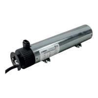
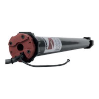
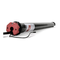
The DVH55B motors are specifically engineered to automate facade blinds, ensuring smooth and controlled movement. They are equipped with electronic limit switches that automatically stop the motor when the blind reaches its fully open or closed position. This eliminates the need for manual adjustment and ensures consistent operation. An integrated emergency stop button provides an additional layer of safety, allowing users to immediately halt the blind's movement to prevent potential damage or accidents. The motor is designed for installation in places shielded from unfavorable weather conditions, emphasizing its suitability for external facade applications.

Important Technical Specifications

  • Power Supply: 230 V / 50 Hz
  • Speed: 26 RPM
  • Max. Time of Work: 6 minutes
  • Operating Temperature: From -10°C to 50°C
  • Protection Degree: IP54
  • Max. Number of Rotations: 00 (This likely indicates an unlimited number of rotations within the operational limits, or it could be a placeholder for a specific, but unstated, maximum. Given the context of electronic limit switches, it suggests continuous operation within the set bounds.)

The motor is designed to be connected to a power source with appropriate cross-section cables, protected by a fast-blow fuse to prevent overload and short-circuits. Installation must be performed by specialists with a 1kV or higher SEP-certified electrician's license, adhering to all regional laws and professional standards.

Usage Features

Motor Assembly:

  1. Mounting Adapters and Rubber Pads: The first step involves attaching the necessary adapters and rubber pads to the motor, preparing it for installation.
  2. Placement in Gutter: The motor is then placed into the blind's gutter system.
  3. Securing Against Shifting: Once positioned, the motor must be securely fastened to prevent any shifting during operation.

Connection: The motor features a standard electrical connection with specific wiring requirements:

  • 1 (Blue): Neutral wire
  • 2 (Black): 1 direction (likely for one direction of movement, e.g., UP)
  • 3 (Brown): 2 direction (likely for the opposite direction of movement, e.g., DOWN)
  • PE (Yellow-Green): Protective wire (ground)

All cables connecting the power receiver to the electric source must be protected from overload and short-circuit effects by devices that automatically disconnect power. The device should be powered with a separate source and protected only with a fast-blow fuse (never a slow-blow fuse). Using an inadequate fuse may void warranty rights.

Limit Positions Setting: The motor's electronic limit switches need to be programmed to define the upper and lower stopping points of the blind. If not set, the motor will stop after running for 1 second.

  • Method 1 (Using UP/DOWN buttons):

    1. Start the motor towards UP and stop it at the desired upper limit position.
    2. Press the UP and DOWN buttons 5 times, at 0.5-second intervals.
    3. Start the motor in the DOWN direction and stop it at the desired lower limit position.
    4. Press the UP and DOWN buttons 5 times, at 0.5-second intervals. This confirms the limit positions have been set.
  • Method 2 (Using Emergency Stop Button): This method can be used when limit positions are not programmed.

    1. Start the motor towards UP.
    2. Press the emergency stop button on the motor to stop it at the upper limit position.
    3. Start the motor in the DOWN direction.
    4. When the shutter reaches the lower end position, start the motor towards UP for a minimum of 5 seconds. This confirms the limit positions have been set.

Deleting Limit Positions: Limit positions can be deleted and then reprogrammed after 10 seconds.

  • Method 1 (When positions are set by Method 1):

    1. Start the motor towards UP.
    2. When the motor stops in the upper limit position, press the UP and DOWN buttons 5 times, at 0.5-second intervals.
    3. Start the motor in the DOWN direction.
    4. When the motor stops in the lower limit position, press the UP and DOWN buttons 5 times, at 0.5-second intervals. This procedure effectively deletes the existing limit positions.
  • Method 2 (When positions are set by Method 2):

    1. Start the motor in the DOWN direction.
    2. Press and hold the emergency stop button on the motor for 5 seconds.
    3. The motor will make a short DOWN move, confirming that the end positions have been removed.

Maintenance Features

  • Regular Electrical System Control: The electrical system control should be performed regularly to detect any signs of use or damage to the motor.
  • Power Disconnection for Maintenance: Electrical supply needs to be disconnected before conducting any maintenance, cleaning, and/or repair work to ensure safety.
  • Liquid Contact: All contact of the motor with any liquids should be reduced to a minimum to prevent damage.
  • Motor and Control System Accessibility: The motor and its control system should be kept out of children's reach for safety.
  • Professional Installation and Servicing: Non-compliance with the specification might cause risk for life or health and can determine improper work of the blind. Installation and any significant repair work should be performed by specialists with appropriate certifications. Failure to follow these instructions can present risks and may result in the loss of warranty rights.
  • Cable Integrity: Motor cables must be secured so that they are not damaged by a working blind.
  • Torque Parameter: The motor's torque parameter should be adequate for the weight of the roller shutter curtain to ensure proper operation and prevent strain.

YOODA DVH55B Specifications

General IconGeneral
BrandYOODA
ModelDVH55B
CategoryEngine
LanguageEnglish

Related product manuals