835965-UIM-C-0814
R-410A
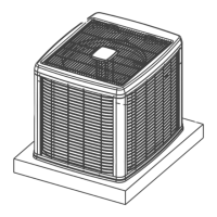
OUTDOOR SPLIT-SYSTEM
AIR CONDITIONING
MODELS: 18 SEER - CZH / AC8B / AL8B SERIES
MODELS: 16 SEER - CZF / AC6B / AL6B SERIES
2 TO 5 TONS
TABLE OF CONTENTS
GENERAL . . . . . . . . . . . . . . . . . . . . . . . . . . . . . . . . . . . . . . . 1
SAFETY . . . . . . . . . . . . . . . . . . . . . . . . . . . . . . . . . . . . . . . . . 1
UNIT INSTALLATION . . . . . . . . . . . . . . . . . . . . . . . . . . . . . . 2
EVACUATION . . . . . . . . . . . . . . . . . . . . . . . . . . . . . . . . . . . . 5
ELECTRICAL CONNECTIONS . . . . . . . . . . . . . . . . . . . . . . . 5
SYSTEM CHARGE . . . . . . . . . . . . . . . . . . . . . . . . . . . . . . . 17
INSTRUCTING THE OWNER . . . . . . . . . . . . . . . . . . . . . . . 17
AC CONTROL BOARD FUNCTIONALITY . . . . . . . . . . . . . 18
WIRING DIAGRAM . . . . . . . . . . . . . . . . . . . . . . . . . . . . . . . 22
START UP SHEET . . . . . . . . . . . . . . . . . . . . . . . . . . . . . . . . 25
LIST OF FIGURES
Typical Installation with Required Clearances . . . . . . . . . . . . . . 3
Tubing Hanger . . . . . . . . . . . . . . . . . . . . . . . . . . . . . . . . . . . . . . . 4
Underground Installation . . . . . . . . . . . . . . . . . . . . . . . . . . . . . . . 4
Heat Protection . . . . . . . . . . . . . . . . . . . . . . . . . . . . . . . . . . . . 5
Typical Field Wiring . . . . . . . . . . . . . . . . . . . . . . . . . . . . . . . . . 6
Communications Harness Connection . . . . . . . . . . . . . . . . . . . 6
Communicating AC with Communicating
Air Handler or Furnace . . . . . . . . . . . . . . . . . . . . . . . . . . . . . . . 7
Communicating AC with Non-Communicating Air Handler
or Furnace using Communicating Interface Control . . . . . . . . . . 7
Thermostat Wiring – Single Stage Air Conditioner
(with AC control) – PSC Air Handler . . . . . . . . . . . . . . . . . . . . . . . 8
Thermostat Wiring – Single Stage Air Conditioner
(with AC control) – VS Air Handler . . . . . . . . . . . . . . . . . . . . . . . 9
Thermostat Wiring – Single Stage Air Conditioner
(with AC control) – Modulating Furnace . . . . . . . . . . . . . . . . . . . 10
Thermostat Chart - Two Stage AC –
Two Stage Variable Speed Furnaces . . . . . . . . . . . . . . . . . . . 11
Thermostat Chart - Two Stage AC –
Two Stage Variable Speed Furnaces . . . . . . . . . . . . . . . . . . . 12
Thermostat Chart - Two Stage AC –
Variable Speed Furnaces . . . . . . . . . . . . . . . . . . . . . . . . . . . . . 13
Thermostat Chart - Two Stage AC –
Variable Speed Furnaces . . . . . . . . . . . . . . . . . . . . . . . . . .. . . . 14
Thermostat Chart - Two Stage AC –
Variable Speed Furnaces . . . . . . . . . . . . . . . . . . . . . . . . . . . . 15
Thermostat Chart - Two Stage AC –
Variable Speed Furnaces . . . . . . . . . . . . . . . . . . . . . . . . . . . . 16
Single Stage Wiring Diagram (2 - 4 Ton) . . . . . . . . . . . . . . . . 22
Single Stage Wiring Diagram (5 Ton) . . . . . . . . . . . . . . . . . . . . 23
Two Stage Wiring Diagram . . . . . . . . . . . . . . . . . . . . . . . . . . . . 24
LIST OF TABLES
R-410A Saturation Properties . . . . . . . . . . . . . . . . . . . . . . . . 18
TEST Input Functionality . . . . . . . . . . . . . . . . . . . . . . . . . . . . 19
Operational Mode Display . . . . . . . . . . . . . . . . . . . . . . . . . . . 19
Status Code Display . . . . . . . . . . . . . . . . . . . . . . . . . . . . . . . 19
Status Code Display . . . . . . . . . . . . . . . . . . . . . . . . . . . . . . . 19
Operational Fault Codes . . . . . . . . . . . . . . . . . . . . . . . . . . . . 20
Sensor or Switch Fault Codes . . . . . . . . . . . . . . . . . . . . . . . 20
Wiring Related Fault Codes . . . . . . . . . . . . . . . . . . . . . . . . . 20
SECTION I: GENERAL
The outdoor units are designed to be connected to a matching indoor
coil with sweat connect lines. Sweat connect units are factory charged
with refrigerant for the highest sales volume evaporator plus 15 feet of
field supplied lines.
Matching indoor coils require a thermal expansion valve. The refriger-
ant charge may need to be changed for some system combinations,
elevation differences, or total line lengths. See tabular data sheet pro-
vided in unit literature packet for charge requirements. Refer to Applica-
tion Data covering “General Piping Recommendations and Refrigerant
Line Length” (Part Number 247077).
SECTION II: SAFETY
This is a safety alert symbol. When you see this symbol on
labels or in manuals, be alert to the potential for personal
injury.
Understand and pay particular attention to the signal words DANGER,
WARNING, or CAUTION.
DANGER indicates an imminently hazardous situation, which, if not
avoided, will result in death or serious injury
.
WARNING indicates a potentially hazardous situation, which, if not
avoided, could result in death or serious injury
.
CAUTION indicates a potentially hazardous situation, which, if not
avoided may result in minor or moderate injury
. It is also used to
alert against unsafe practices and hazards involving only property dam-
age.