EasyManua.ls Logo

York CZF User Manual

York CZF
26 pages
To Next Page IconTo Next Page
Page #1 background imageLoading...
Page #1 background image
835965-UIM-C-0814
R-410A
OUTDOOR SPLIT-SYSTEM
AIR CONDITIONING
MODELS: 18 SEER - CZH / AC8B / AL8B SERIES
MODELS: 16 SEER - CZF / AC6B / AL6B SERIES
2 TO 5 TONS
INSTALLATION MANUAL
®
TABLE OF CONTENTS
GENERAL . . . . . . . . . . . . . . . . . . . . . . . . . . . . . . . . . . . . . . . 1
SAFETY . . . . . . . . . . . . . . . . . . . . . . . . . . . . . . . . . . . . . . . . . 1
UNIT INSTALLATION . . . . . . . . . . . . . . . . . . . . . . . . . . . . . . 2
EVACUATION . . . . . . . . . . . . . . . . . . . . . . . . . . . . . . . . . . . . 5
ELECTRICAL CONNECTIONS . . . . . . . . . . . . . . . . . . . . . . . 5
SYSTEM CHARGE . . . . . . . . . . . . . . . . . . . . . . . . . . . . . . . 17
INSTRUCTING THE OWNER . . . . . . . . . . . . . . . . . . . . . . . 17
AC CONTROL BOARD FUNCTIONALITY . . . . . . . . . . . . . 18
WIRING DIAGRAM . . . . . . . . . . . . . . . . . . . . . . . . . . . . . . . 22
START UP SHEET . . . . . . . . . . . . . . . . . . . . . . . . . . . . . . . . 25
LIST OF FIGURES
Typical Installation with Required Clearances . . . . . . . . . . . . . . 3
Tubing Hanger . . . . . . . . . . . . . . . . . . . . . . . . . . . . . . . . . . . . . . . 4
Underground Installation . . . . . . . . . . . . . . . . . . . . . . . . . . . . . . . 4
Heat Protection . . . . . . . . . . . . . . . . . . . . . . . . . . . . . . . . . . . . 5
Typical Field Wiring . . . . . . . . . . . . . . . . . . . . . . . . . . . . . . . . . 6
Communications Harness Connection . . . . . . . . . . . . . . . . . . . 6
Communicating AC with Communicating
Air Handler or Furnace . . . . . . . . . . . . . . . . . . . . . . . . . . . . . . . 7
Communicating AC with Non-Communicating Air Handler
or Furnace using Communicating Interface Control . . . . . . . . . . 7
Thermostat Wiring – Single Stage Air Conditioner
(with AC control) – PSC Air Handler . . . . . . . . . . . . . . . . . . . . . . . 8
Thermostat Wiring – Single Stage Air Conditioner
(with AC control) – VS Air Handler . . . . . . . . . . . . . . . . . . . . . . . 9
Thermostat Wiring – Single Stage Air Conditioner
(with AC control) – Modulating Furnace . . . . . . . . . . . . . . . . . . . 10
Thermostat Chart - Two Stage AC –
Two Stage Variable Speed Furnaces . . . . . . . . . . . . . . . . . . . 11
Thermostat Chart - Two Stage AC –
Two Stage Variable Speed Furnaces . . . . . . . . . . . . . . . . . . . 12
Thermostat Chart - Two Stage AC –
Variable Speed Furnaces . . . . . . . . . . . . . . . . . . . . . . . . . . . . . 13
Thermostat Chart - Two Stage AC –
Variable Speed Furnaces . . . . . . . . . . . . . . . . . . . . . . . . . .. . . . 14
Thermostat Chart - Two Stage AC –
Variable Speed Furnaces . . . . . . . . . . . . . . . . . . . . . . . . . . . . 15
Thermostat Chart - Two Stage AC –
Variable Speed Furnaces . . . . . . . . . . . . . . . . . . . . . . . . . . . . 16
Single Stage Wiring Diagram (2 - 4 Ton) . . . . . . . . . . . . . . . . 22
Single Stage Wiring Diagram (5 Ton) . . . . . . . . . . . . . . . . . . . . 23
Two Stage Wiring Diagram . . . . . . . . . . . . . . . . . . . . . . . . . . . . 24
LIST OF TABLES
R-410A Saturation Properties . . . . . . . . . . . . . . . . . . . . . . . . 18
TEST Input Functionality . . . . . . . . . . . . . . . . . . . . . . . . . . . . 19
Operational Mode Display . . . . . . . . . . . . . . . . . . . . . . . . . . . 19
Status Code Display . . . . . . . . . . . . . . . . . . . . . . . . . . . . . . . 19
Operational Fault Codes . . . . . . . . . . . . . . . . . . . . . . . . . . . . 20
Sensor or Switch Fault Codes . . . . . . . . . . . . . . . . . . . . . . . 20
Wiring Related Fault Codes . . . . . . . . . . . . . . . . . . . . . . . . . 20
SECTION I: GENERAL
The outdoor units are designed to be connected to a matching indoor
coil with sweat connect lines. Sweat connect units are factory charged
with refrigerant for the highest sales volume evaporator plus 15 feet of
field supplied lines.
Matching indoor coils require a thermal expansion valve. The refriger-
ant charge may need to be changed for some system combinations,
elevation differences, or total line lengths. See tabular data sheet pro-
vided in unit literature packet for charge requirements. Refer to Applica-
tion Data covering “General Piping Recommendations and Refrigerant
Line Length” (Part Number 247077).
SECTION II: SAFETY
This is a safety alert symbol. When you see this symbol on
labels or in manuals, be alert to the potential for personal
injury.
Understand and pay particular attention to the signal words DANGER,
WARNING, or CAUTION.
DANGER indicates an imminently hazardous situation, which, if not
avoided, will result in death or serious injury
.
WARNING indicates a potentially hazardous situation, which, if not
avoided, could result in death or serious injury
.
CAUTION indicates a potentially hazardous situation, which, if not
avoided may result in minor or moderate injury
. It is also used to
alert against unsafe practices and hazards involving only property dam-
age.
Question and Answer IconNeed help?

Do you have a question about the York CZF and is the answer not in the manual?

York CZF Specifications

General IconGeneral
Cooling Capacity9, 000 - 36, 000 BTU
TypeMini-Split
Power Supply230V, 60Hz
RefrigerantR410A
Indoor Unit Dimensions (HxWxD)Varies by model
Outdoor Unit Dimensions (HxWxD)Varies by model
Indoor Unit WeightVaries by model
Outdoor Unit WeightVaries by model

Summary

Safety

General Safety Precautions

Understand and pay attention to signal words for potential hazards like DANGER, WARNING, and CAUTION.

Unit Installation

Location Requirements

Guidelines for selecting an appropriate location for the outdoor unit, considering clearances and service access.

Add-on Replacement/Retrofit

Procedures for replacing R-22 systems with R-410A equipment, including component change-outs.

Ground Installation

Proper installation methods for units placed at ground level, ensuring stability and level positioning.

Roof Installation

Structural considerations for mounting units on a roof, including load capacity and vibration isolation.

Wall Mount Installation

Requirements for secure wall mounting and vibration isolation, addressing structural integrity.

Unit Placement

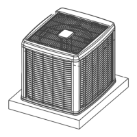
Steps for positioning and securing the outdoor unit on its base after unpacking.

Liquid Line Filter-Drier

Location and replacement information for the liquid line filter-drier.

TXV Installations

Basic installation steps for a thermostatic expansion valve (TXV) kit.

Piping Connections

Precautions During Line Installation

Best practices for routing and installing refrigerant lines to prevent damage, kinks, and restrictions.

Precautions During Brazing of Lines

Essential steps and precautions for brazing copper refrigerant lines using inert gas.

Precautions During Brazing Service Valve

Methods to protect service valves from heat damage during brazing operations.

System Evacuation

Evacuation Procedure

Instructions for evacuating the system to 500 microns or less and leak testing.

Electrical Connections

General Information and Grounding

Electrical supply requirements, grounding, wire sizing, and code compliance.

Field Connections Power Wiring

Steps for connecting the unit's power supply wiring from the disconnect switch.

Field Connections Control Wiring (Serial Communication)

Connecting the communications harness for serial communication systems.

Field Connections Control Wiring (Conventional)

Connecting low voltage control wiring for conventional thermostat setups.

Dehumidification Control

Indoor CFM Configuration

Setting indoor fan (CFM) for optimal system operation and dehumidification.

System Charge

Subcooling Charging Method

Method for charging the system using subcooling measurements as per the rating plate.

Owner Information and Maintenance

Instructing the Owner

Guidance on system operation, warranty registration, and owner's manual.

Routine Maintenance

Routine maintenance tasks for the outdoor unit, including coil cleaning and lubrication.

AC Control Board Functionality

Anti-Short Cycle Delay

Explanation of the anti-short cycle delay for compressor protection.

Low Voltage Detection

How the control detects and responds to low voltage conditions to prevent component damage.

Test Input Functionality

Functionality of the TEST input connector for installation and service procedures.

LED Diagnostic Indicators

Interpretation of LED indicators (Red, Green, Yellow) for status and fault information.

Operational Mode Detection

How the control determines the operating mode based on terminal connections.

Operational Mode Display

Display of operational modes using onboard LEDs when TEST pins are connected.

Status Code Display

Codes displayed by LEDs to indicate operational status, not faults.

Fault Code Display

How the control displays fault codes using LED flashing patterns.

Sensor or Switch Fault Codes

Fault codes related to sensor or switch issues, indicated by LED patterns.

Wiring Related Fault Codes

Fault codes indicating wiring or jumper configuration problems.

Lockout Modes

Conditions and actions for soft and hard lockouts, including reset procedures.

Cooling Operation

Detailed explanation of first and second stage cooling operations and compressor control.

High-Pressure Switch Fault

How the control handles high-pressure switch faults and lockout conditions.

Low-Pressure Switch Fault

How the control handles low-pressure switch faults and lockout conditions.

Outdoor Ambient Temperature Sensor

Function of the outdoor ambient temperature sensor in communication applications.

Wiring Diagrams

Single Stage Wiring Diagram (2-4 Ton)

Electrical schematic for 2 to 4 ton single stage units, showing component connections.

Single Stage Wiring Diagram (5 Ton)

Electrical schematic for 5 ton single stage units, illustrating wiring.

Two Stage Wiring Diagram

Electrical schematic for two stage units, detailing component wiring.

Start-Up Sheet

Equipment Data Entry

Fields for recording essential equipment specifications during start-up.

Electrical Connections Verification

Checks for correct line voltage and low voltage wiring connections.

Heating Setup and Venting

Configuration of heating type, gas pressure, and venting system.

Related product manuals