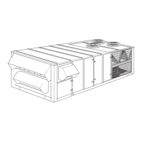
Do you have a question about the York MILLENNIUM Y22 and is the answer not in the manual?
General safety advice, notes, cautions, and warnings for installation and servicing.
Specific safety precautions related to flammable vapors and gas leaks.
Hazards related to system pressure and electrical components; personnel qualifications.
Procedure for inspecting units for damage during transit upon receipt.
Certifications and design standards for the unit's use.
Conformance requirements for installation codes and standards.
Guidelines for selecting a suitable outdoor installation location for optimal performance.
Instructions for safely moving and rigging the unit using chains, spreaders, and lifting lugs.
Required clearances for unit operation, servicing, combustion, and ventilation air.
Guidelines for designing and connecting ductwork, including flexible joints and noise reduction.
Information on factory-installed hoods for units without an economizer.
Instructions for installing and sealing economizer outside air intake hoods.
Details on factory-installed hoods and dampers for exhaust air.
Instructions for installing and protecting the condensate drain connection.
Identification of hinged doors providing access to serviceable components.
Information on factory adjustment and readiness of compressors for operation.
Requirements for filter installation, maintenance, and operational impact.
Guidelines for thermostat placement and wiring for constant volume units.
Guidelines for space sensor placement for VAV systems.
Conformance to NEC codes for field wiring, grounding, and voltage tolerances.
Specifications for power wiring connections, including wire gauge and entry points.
Information on the Energy Recovery Ventilation unit, its assembly, and control integration.
Guidelines for sizing gas piping based on flow rate, gas gravity, and run length.
Routing and connecting the gas supply line, including drip legs and unions.
Instructions for installing vent and combustion air hoods and flue extensions for gas heat.
Description of electric heat units, including capacity steps for constant volume and VAV units.
Information on factory-installed hot water coils and installer responsibilities for piping and valves.
Details on entering hot water piping through the floor and sealing access holes.
Information on factory-installed single-row steam coils and safety warnings.
Steam piping entry through the floor and sealing access holes to prevent condensate leakage.
Field installation of tubing for pressure sensing for VFDs and IGVs.
Connecting building pressure sensors for modulating power exhaust control.
Information and tables for correcting performance data based on altitude and temperature.
Procedure for checking and ensuring correct compressor rotation direction.
Checks and adjustments for supply air fan components and operation.
Instructions for adjusting belt tension for proper fan operation and drive life.
Steps for balancing air distribution by adjusting supply and return duct resistances.
Steps for adjusting supply air fan drive for desired CFM using sheave pitch diameter.
Notes on thermostat and space sensor offsets and parameter review.
Step-by-step instructions for safely lighting the main burners on the unit.
Procedure for safely shutting down the unit and its gas valve.
Essential checks after initial start-up for gas leaks and proper pressures.
How to adjust gas pressure using the regulator screw for correct manifold pressure.
Steps for accessing and servicing burners, pilots, and orifices.
Ensuring temperature rise is within specified limits for furnace operation.
Method for determining gas consumption rate using a test dial gas meter.
Factory readiness and rotation checks for compressors.
Procedure for checking the oil level in compressor sight glasses.
Verifying and tightening electrical connections in the unit control box.
Checking condenser fan rotation and potential phasing issues.
General description of the Simplicity control's features and functions for HVAC control.
Description of Occupied, Unoccupied, and Recovery modes and their functionalities.
How the control manages mechanical cooling stages based on ambient and operating conditions.
Control logic for gas heat stages, ignition, and safety interlocks.
Control logic for electric heat stages, including auto-reset and backup limits.
Control strategy for modulating hot water valves based on SAT setpoints.
Control of economizer dampers for free cooling and temperature maintenance.
Overview of VAV unit operation modes and controls.
Detailed modes for VAV unit operation including scheduling and overrides.
How the MWUP mode starts and operates before scheduled occupancy.
Control logic for MWUP, including RAT setpoints and fan operation.
How the control selects modes and responds to thermostat and sensor inputs.
How compressors are grouped and staged for cooling operation based on unit configuration.
How economizer interacts with thermostat calls and SAT control.
Fan off delay logic during heating when thermostat signal is de-energized.
Minimum run and off times for heating stages.
How thermostats control heating with hydronic coils using SAT setpoints.
How the control uses thermostats and space sensors for heating control.
Control strategies for static pressure using Inlet Guide Vanes or VFDs.
Control of economizer dampers for ventilation and free cooling based on OAT and SAT.
Control methods for power exhaust systems, including modulating and VFD options.
How the head pressure control option manages condenser fan speed for cooling.
Step-by-step operation of the head pressure control during cooling cycles.
How Intelli-Start optimizes morning warm-up based on building recovery times.
Equalizing run time on compressors, except for specific options.
Introduction to Simplicity control modes and their operational logic.
How the control checks the Air Proving Switch and handles failures.
How the economizer modulates SAT to maintain comfort during satisfied periods.
How the PI algorithm modulates dampers to maintain SAT within specified bands.
How the control stages heating or cooling to assist economizer in maintaining SAT.
Control of SAT and hot water valve for hydronic heating using SAT setpoints.
Protection against freezing of hot water coils, including valve override and alarms.
How the control uses thermostat inputs for cooling stages and fan control.
Fan off delay logic during heating when thermostat signal is de-energized.
Minimum run and off times for heating stages.
How thermostats control heating with hydronic coils using SAT setpoints.
How the control uses thermostats and space sensors for heating control.
How the control uses space temperature sensors for CV and VAV operations.
Default operation of power exhaust upon building pressure sensor failure.
Unit shutdown procedure when duct static pressure sensor fails.
Disabling of Demand Ventilation mode if IAQ sensor fails.
Alarm condition for SAT deviating from setpoint during heating.
Alarm condition for SAT deviating from setpoint during cooling.
Error handling for supply fan issues, linked to Air Proving Switch.
Error handling for compressor safety monitoring and lockouts.
Alarm triggered by a dirty filter switch indicating a clogged filter.
Alarm triggered when duct static pressure exceeds a high limit.
Alarm triggered by freeze stat for hot water coils.
How thermostats control VAV cooling and heating setpoints and occupancy.
Using a space sensor for SAT reset in cooling and zone temp control for heating.
VAV control using external commands for occupancy and warm-up.
Supply fan off delay logic specific to VAV operations.
Thermostat control for occupied heating in VAV systems.
Control of unoccupied heating via thermostat and economizer damper.
Thermostat control for cooling, managing setpoints to prevent conflicts.
Thermostat control for unoccupied cooling, including economizer operation.
Space sensor control for occupied heating, using SAT reset setpoints.
Space sensor control for unoccupied heating, managing SAT and VAV boxes.
Space sensor control for occupied cooling, using SAT setpoints.
Using PI algorithm to control supply duct static pressure via Vanes or VFD.
Initiation of Morning Warm Up mode based on schedule and Intelli-Start.
Control logic for MWUP, including RAT setpoints and fan operation.
How the Space Sensor compares temperature to setpoints for unoccupied heating/cooling.
Space sensor comparison of temperature to setpoints for occupied heating/cooling.
Enabling/disabling SAT control and its priority over other zone controls.
How cooling SAT control prioritizes and manages compressor operation.
How economizer dampers mix air for cooling based on energy, ventilation, and static pressure.
Setting the minimum outdoor damper position for ventilation in occupied mode.
Economizer damper position during heating and cooling modes.
SAT setpoints used during cooling when economizer is enabled for free cooling.
Methods for determining economizer suitability based on sensor availability and data.
Methods for determining economizer suitability: Differential, Outside Enthalpy, and Outside Temp.
How compressors operate when the economizer is active or saturated.
Procedure for staging and turning off compressors based on economizer saturation and SAT.
How the control handles cooling lockout when OAT rises above a setpoint.
Using economizer dampers to maintain SAT during cooling, minimizing compressor cycling.
Using economizer dampers to decrease SAT during heating, minimizing stage cycling.
When economizer operation is used in VAV cooling modes.
Control strategy for IAQ levels using economizer damper modulation.
Fixed speed power exhaust fan control slaved to economizer damper position.
Modulating exhaust damper to maintain building static pressure using a closed-loop algorithm.
How the ERV exchanges heat and interacts with economizer and VAV systems.
How the Millennium Simplicity control uses its clock and calendar for operations.
Monitoring compressor status via VAC circuits for safeties and lockouts.
Alarm condition for SAT deviating from setpoint during heating.
Alarm condition for SAT deviating from setpoint during cooling.
Error handling for supply fan issues, linked to Air Proving Switch.
Error handling for compressor safety monitoring and lockouts.
Alarm triggered by a dirty filter switch indicating a clogged filter.
Alarm triggered when duct static pressure exceeds a high limit.
Alarm triggered by freeze stat for hot water coils.
Interpretation of status LED flash patterns for troubleshooting unit conditions.
Overview of common failure modes, error logging, and default system behavior.
How sensor failures affect control, default operations, and error indications.
Alarm conditions for SAT, Fan, Compressor, and Filter status.
Introduction to the Simplicity controller, its features, and benefits.
Explanation of LED indicators for control status and alarms.
How the control stores and displays the most recent alarms and maintenance data.
How analog sensor values are converted to binary code for computer processing.
Explanation of software programming, memory types (EPROM, RAM), and firmware.
Description of Proportional-Integral control loops for modulating analog outputs.
Understanding hardware and software fault tolerance in Simplicity control.
Connecting multiple units to a network for remote monitoring and control via MODBUS.
Interface between Modbus and BACnet systems for data exchange.
Description of the Simplicity microprocessor-based controller for HVAC applications.
Identifying rooftop units on a network using address buttons and unique identifiers.
Glossary of acronyms and terms used in the Simplicity control manual.
Detailed descriptions of various analog inputs (ST, OAT, SAT, RAT, etc.) and their functions.
Descriptions of binary inputs like APS, Compressor Overloads, and Thermostat signals.
Details on analog outputs (AO) for controlling devices like VFDs and dampers.
Control of the modulating economizer actuator via 2-10 VDC signal.
Wiring details for VFDs and Inlet Guide Vanes for fan speed control.
Descriptions of binary outputs like Fan relays, Heat/Cool stages, and alarms.
Definitions and functions of parameters adjustable via interfaces.
Step-by-step guide to setting the unit's internal clock and date.
How to navigate and change parameter values using the control buttons.
Field adjustments required for commissioning, including setpoints and option enabling.
Listing and explanation of system parameters like Compressors, Heat Stages, and Hydronic Heating.
Settings for SAT control, Power Exhaust, Economizer damper positions, and setpoints.
Settings for RAH sensor, Economizer Loading, Duct Static, and Warm-Up parameters.
Parameters for VAV cooling and heating SAT setpoints, and reset setpoints.
Settings for Comfort Ventilation, Heating/Cooling Lockout on OAT, and Freeze Protection.
Parameters for Demand Ventilation, IAQ, Cooling/Heating Modes, and Space Setpoint Offset.
Settings for commissioning tests, fan delays, and sensor enable options.
Details on refrigerant charge, sight glasses, and filter driers for each system.
Information on compressor protection, motor types, and lubrication.
How the pressure switch verifies combustion air flow for safe operation.
Safety switch sensing flame or excess heat in burner compartment for lockout.
Routine tasks including filter inspection/replacement and burner cleaning.
Guidelines for inspecting, replacing, and sizing filters.
Information on lubrication requirements for different motor types.
Visual check of burner flame and cleaning procedures.
Inspecting and cleaning the discharge outlet for soot and dirt.
Steps for cleaning flue passages and heating elements using brushes and air.
Steps to secure owner approval, demonstrate operation, and explain controls.
Graph showing pressure drop across the evaporator coil versus supply air CFM for 25-ton units.
Graph showing pressure drop across the evaporator coil versus supply air CFM for 30/40-ton units.
| Brand | York |
|---|---|
| Model | MILLENNIUM Y22 |
| Category | Air Conditioner |
| Language | English |


 Loading...